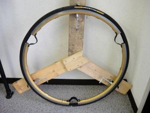
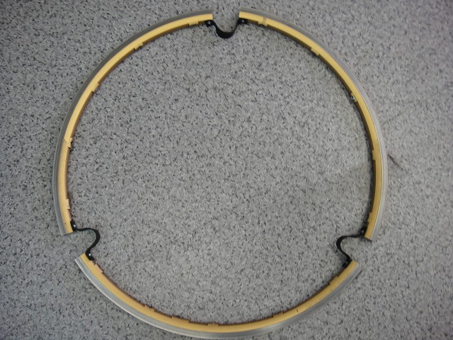
The tubular tire stretching machine "Stretcher Y"
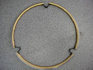
is divided into a Y-shaped base section and a rim section.
For the rim section, I swap in better examples as they become available.
If you divide a circle evenly into 3 parts, you get 120° phase intervals,
but it's convenient if I can get a rim divided at around 110° phase.
The previous rim is the third generation, but originally it was 20H.
With a 20H rim, dividing at around 6.5H gives me the rim section I need for the right angle.
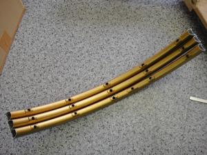
This fourth generation version uses a 16H from my Shamal Ultra tubular front wheel,
and with a 16H, dividing at around 5⅔H (as shown in the image above) works just right.
Yeah, this looks great.

↑A matter of pride—genuine leather (I tried thick rubber plates and all sorts of things, but this is the best)
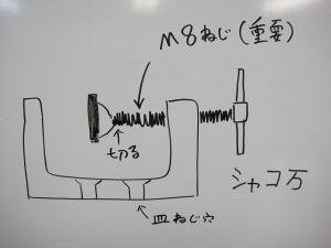
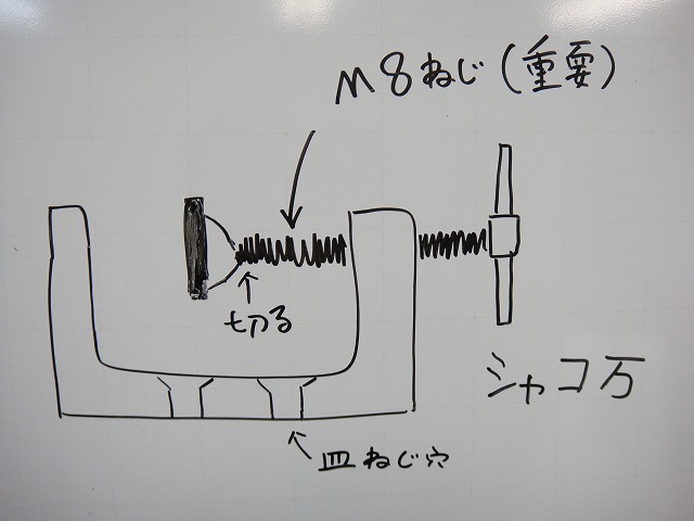
For the bench vise I attach to the Y-shaped base,
I use a clamp from a maker called EIGER.
I cut off the pressing plate at the end of the screw.
M8 thread diameter is the most convenient (reason to follow).
This type of tool is called a bench vise, or shako-man,
and if you walk into a shop and say "shako-man, please!"
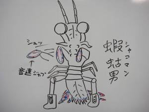
↑you might end up sparring with this guy, so be careful.
A mantis punch is faster than the human eye can follow.

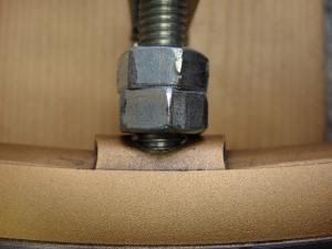
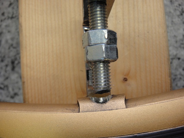
I attach a nut to the vise screw.
I use a double nut (Wnut) to prevent loosening from rotation.
If the rim doesn't have enough screw length inside it,
it might come loose during use, so I leave some screw threads sticking out past the nut.
Drill out the rim hole to match the vise screw diameter.
The reason for M8 is that M6 is too thin to press the rim properly, and M10 makes the hole too large.
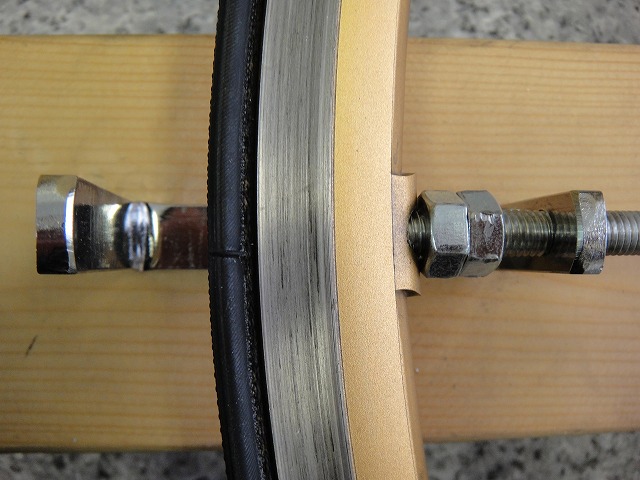
Requirement #1 for the rim side:
The rim crown needs to be as flat as possible since the nut scrapes against it.
It's surprisingly hard to find rims that meet this criterion.
Even WO (wired-on) rims are OK if you sand down the cut edges.

Requirement #2 for the rim side:
The vise screw needs to penetrate the rim sufficiently,
so classical low-profile rims aren't suitable.
You need a rim with some decent height.
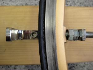
Before stretching
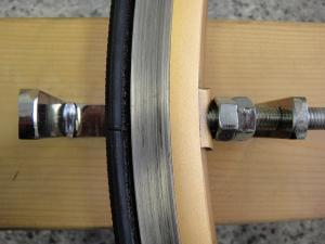
After stretching
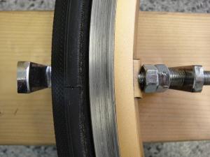
Pump in air
That's it
Bonus

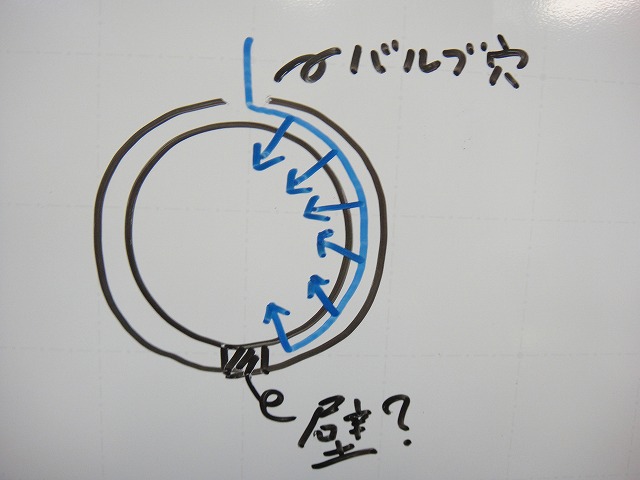
With this type of rim, you pick up nipples one-by-one with a magnet,
but there's a "wall" of sorts at the rim seam,
and nipples can't pass through it—something I knew from experience.
So when doing a test assembly, I have to pass nipples through starting from the side closest to the opposite side of the valve hole, doing one side at a time.

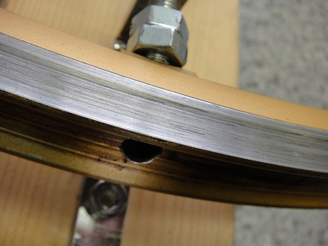
↑The rim seam section
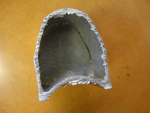
↑There's a wall. This is the first time I've actually seen it.
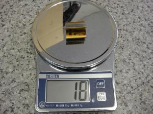
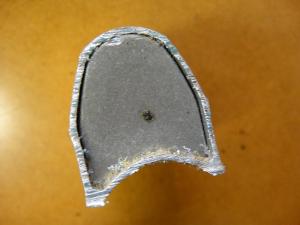
I weighed the cut end piece from the seam section.

↑I weighed a cut end piece of similar length from elsewhere.
With some measurement fluctuation, the "wall" weighs about 12g.
I suspect this is intentional—a deliberate design feature to balance the weight against the valve side.

is divided into a Y-shaped base section and a rim section.
For the rim section, I swap in better examples as they become available.
If you divide a circle evenly into 3 parts, you get 120° phase intervals,
but it's convenient if I can get a rim divided at around 110° phase.
The previous rim is the third generation, but originally it was 20H.
With a 20H rim, dividing at around 6.5H gives me the rim section I need for the right angle.
This fourth generation version uses a 16H from my Shamal Ultra tubular front wheel,
and with a 16H, dividing at around 5⅔H (as shown in the image above) works just right.
Yeah, this looks great.
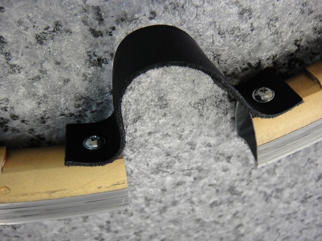
↑A matter of pride—genuine leather (I tried thick rubber plates and all sorts of things, but this is the best)
For the bench vise I attach to the Y-shaped base,
I use a clamp from a maker called EIGER.
I cut off the pressing plate at the end of the screw.
M8 thread diameter is the most convenient (reason to follow).
This type of tool is called a bench vise, or shako-man,
and if you walk into a shop and say "shako-man, please!"
↑you might end up sparring with this guy, so be careful.
A mantis punch is faster than the human eye can follow.
I attach a nut to the vise screw.
I use a double nut (Wnut) to prevent loosening from rotation.
If the rim doesn't have enough screw length inside it,
it might come loose during use, so I leave some screw threads sticking out past the nut.
Drill out the rim hole to match the vise screw diameter.
The reason for M8 is that M6 is too thin to press the rim properly, and M10 makes the hole too large.

Requirement #1 for the rim side:
The rim crown needs to be as flat as possible since the nut scrapes against it.
It's surprisingly hard to find rims that meet this criterion.
Even WO (wired-on) rims are OK if you sand down the cut edges.
Requirement #2 for the rim side:
The vise screw needs to penetrate the rim sufficiently,
so classical low-profile rims aren't suitable.
You need a rim with some decent height.

Before stretching
After stretching

Pump in air

That's it
Bonus
With this type of rim, you pick up nipples one-by-one with a magnet,
but there's a "wall" of sorts at the rim seam,
and nipples can't pass through it—something I knew from experience.
So when doing a test assembly, I have to pass nipples through starting from the side closest to the opposite side of the valve hole, doing one side at a time.
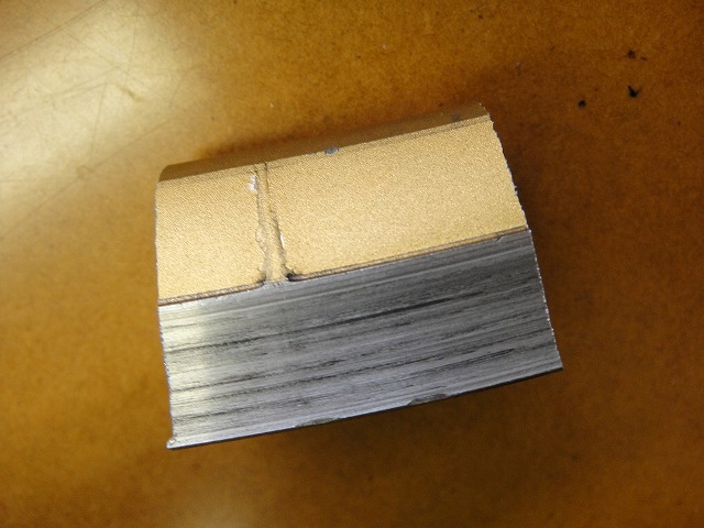
↑The rim seam section


↑There's a wall. This is the first time I've actually seen it.
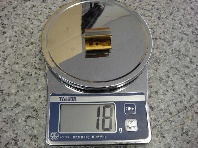
I weighed the cut end piece from the seam section.
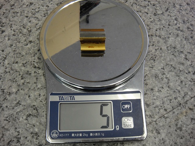
↑I weighed a cut end piece of similar length from elsewhere.
With some measurement fluctuation, the "wall" weighs about 12g.
I suspect this is intentional—a deliberate design feature to balance the weight against the valve side.