I received Aeolos 51mm high rim tubeless ready wheels from a customer.
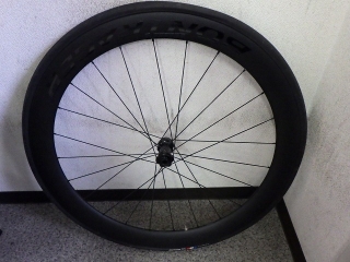
First, the front wheel.
Before that though.
This is a trivial observation, but
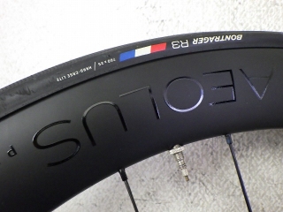
the text and logos printed on the rim have gravity direction oriented in three ways:
toward the inside of the wheel,
toward the outside of the wheel, or
in a single directional orientation.
On this wheel, the Aeolos text is oriented outward.
The single directional type is like Campagnolo wheels, where
when BORA is readable right-side-up at the top of the wheel,
CAMPAGNOLO is also readable right-side-up
at the bottom of the wheel.
In this case, when the wheel rotates and BORA becomes inverted,
CAMPAGNOLO also becomes upside-down.
Now, those are about the rim. With tires, in almost all cases
the text gravity is directed inward toward the wheel.
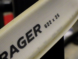
But Bontrager tires have text oriented outward,
and the appearance is still unfamiliar to me.
When you want to read the text in the normal orientation with the label near the contact patch,
you'd practically need to crawl on the ground to see it.
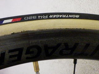
↑This is an older Aeolos 3 rim brake wheel I'm working on for a different customer,
with a tubular tire that also has the label oriented outward.

Anyway, there was significant centering offset.
I don't mean to say that cheap wheels should have sloppy workmanship,
but given the wheel's price point,
the amount of centering offset is absurdly careless.
There was almost no lateral runout.
If I were to correct the centering by tightening,
I'd need to further tighten the high-tension side (left, rotor-side).
That's much more difficult than tightening the low-tension side,
but this front wheel had loose tension,
and the rim easily tensioned from the right side,
crossed center, and shifted to the left.
So starting from that state, I tightened the right side to center it,
meaning not a single nipple was left untightened from the original state.
I've been told that if I think tension is loose, I can tighten it,
so within reasonable limits I tensioned it as much as I could.
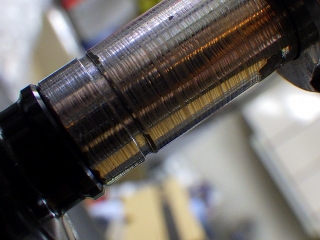
I thought I'd missed taking a photo, but I actually have an image showing the offset reversed from the original direction.
In the original state, the measurement taken at the left end
showed a gap at the hub side of the right end,
but the image above shows
it reversed by tightening the left side from that point.
From that state, I tightened the right side to center it.
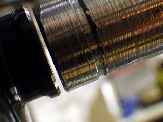
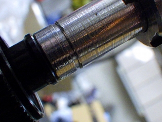
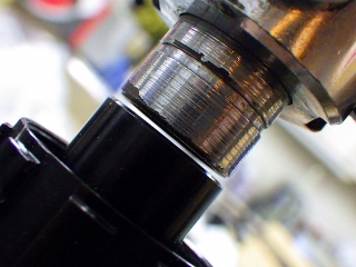
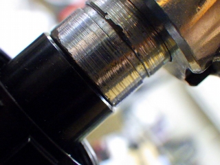
This wheel has nipples with gripping surfaces on the outer circumference,
and since it didn't use a tape-type rim tape,
I removed the rim tape and adjusted by gripping the outer circumference of the nipples.
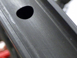
Although it's a tubeless ready rim,
it has no hump and the bead-lock groove has shallow radii,
so it uses a rim tape that's typically incompatible with tubeless ready rims—
a stretch-band type rim tape.
It's OEM, with wide width, good thickness, and fairly stiff material,
so it doesn't get dragged into the rim depression and shrink below the rim's inner width.
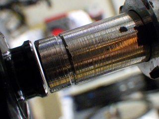
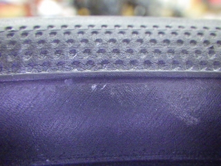
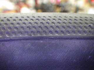
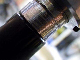
Looking at areas discolored by contact with the tire bead,
for example in the image above, only the bottom edge
shows traces of contact with the rim's sidewall,
indicating that at all phases of rotation,
the tape didn't stay perfectly centered.
But at this level, there's no problem at all.
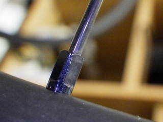
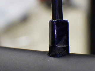
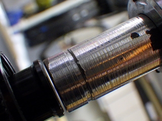
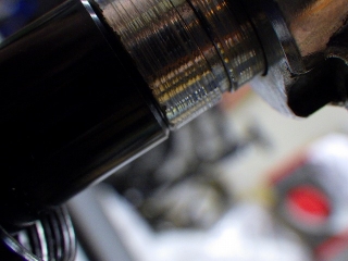
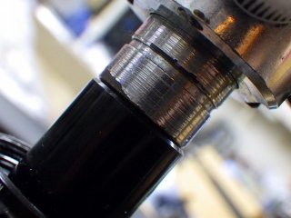
On both wheels, I adjusted only by gripping the outer circumference,
but some of the inner-side gripping surfaces show
wear marks from tool contact in the loosening direction.
Whether this came from the factory or developed during truing work,
I can't say for certain.
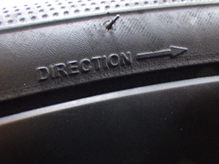
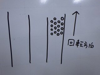
Regarding the tire tread pattern,
even though this tire has no directional distinction in the tread's water-shedding pattern,
it does have a rotation direction specified.
Following that specification, the arrangement would have
an arrow only on the right side of the tire.
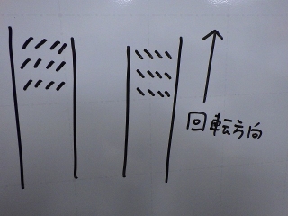
I said the tread pattern has no directional basis, but
at least for the front and rear tires on this wheel,
I could distinguish left from right without looking at the arrow.
On Specialized tires,
there's a sand-grain-like tread pattern on both sides of the center slick,
and looking closely, some show distinguishable water-shedding direction.
This tread pattern is raised and protrudes higher than the slick surface
(not quite what you'd call a knob, but close to it).
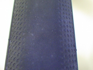
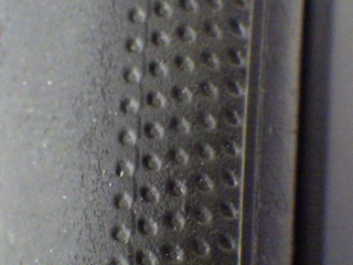
In contrast, the Bontrager tire in this case
has round tread patterns arranged on the sides of the center slick.
This pattern isn't raised but recessed,
creating a golf-ball dimple effect.
The right side is.
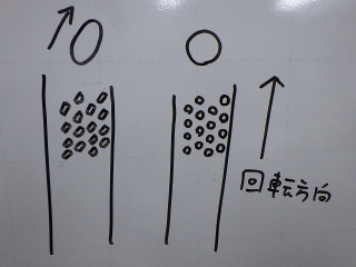
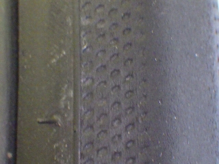
Strangely, on the left side they become elongated slots oriented for water-shedding,
with differences distinct enough to visually tell them apart.
I don't think this has any intentional performance purpose.
Could it be from mold wear during manufacturing?
Since the arrow on the tire side appears only on one side (right),
and that comes from mold transfer, if only one mold exists in the world for this tire,
the relationship between the tread pattern shape and arrow should remain constant.
Or perhaps this developed from extended use?
Like maybe continuous banking practice that caused tread wear on one side only.
By the way, counter-clockwise-only tires meant exclusively for track banking
do actually exist (→see here).
→→→Rotation direction→→→
Front wheel tire viewed from the right side
←←←Rotation direction←←←
Front wheel tire viewed from the left side
↑↑↑Rotation direction↑↑↑
Rear wheel tire viewed from above
Right side of the rear tire viewed from above
Left side of the rear tire viewed from above
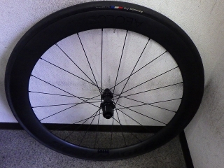
Anyway, moving on to the rear wheel.
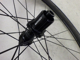
Both wheels use DT straight-spoke hubs for 24H,
all-black aerolite straight spokes, radially laced on both sides with forced 2-cross.
If I were to increase spoke proportion on the side with steeper spoke angles
or tie the spokes on the final cross sections where both front and rear wheels are braced,
they could transform beyond their as-shipped limits.
But since this is just an inspection, I won't go that far.

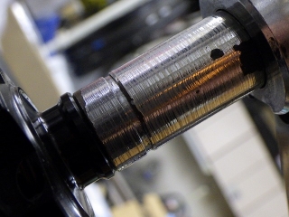
The rear wheel was the opposite of the front—it had fairly tight tension for as-shipped,
but there was some runout.
Whether there's a history of truing after factory assembly,
or if someone attempted intentional tightening, I can't say.
At the phase shown in the image above, it checks out as perfectly centered,
but if I look around, I'm likely to find phases where it's off by a full sheet of paper or more.
Without worrying about the centering offset,
I finished truing with a freewheel-side tightening tendency.
The centering offset that exists now
I interpret entirely as a bonus from anti-freewheel side tightening.
I centered it.
The front wheel has tightened considerably from its original state,
but the rear wheel doesn't show the kind of dramatic change you'd call a "transformation."
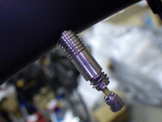
Only the rear wheel had a Specialized tube installed.
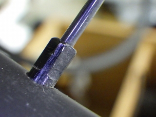
The outer diameter of a threadless valve and
the outer diameter at the thread crest of a threaded valve are the same,
but partway along, the unthreaded portion of a threadless valve
has the same diameter as the thread valley of a threaded valve, so the pump head grip is poor,
and with portable inflators that lack a locking ring mechanism that tightens when you flip the lever,
air entry can be quite difficult—something to watch out for.
For details (→see here)

First, the front wheel.
Before that though.

This is a trivial observation, but
the text and logos printed on the rim have gravity direction oriented in three ways:
toward the inside of the wheel,
toward the outside of the wheel, or
in a single directional orientation.
On this wheel, the Aeolos text is oriented outward.
The single directional type is like Campagnolo wheels, where
when BORA is readable right-side-up at the top of the wheel,
CAMPAGNOLO is also readable right-side-up
at the bottom of the wheel.
In this case, when the wheel rotates and BORA becomes inverted,
CAMPAGNOLO also becomes upside-down.
Now, those are about the rim. With tires, in almost all cases
the text gravity is directed inward toward the wheel.
But Bontrager tires have text oriented outward,
and the appearance is still unfamiliar to me.
When you want to read the text in the normal orientation with the label near the contact patch,
you'd practically need to crawl on the ground to see it.

↑This is an older Aeolos 3 rim brake wheel I'm working on for a different customer,
with a tubular tire that also has the label oriented outward.


Anyway, there was significant centering offset.

I don't mean to say that cheap wheels should have sloppy workmanship,
but given the wheel's price point,
the amount of centering offset is absurdly careless.
There was almost no lateral runout.
If I were to correct the centering by tightening,
I'd need to further tighten the high-tension side (left, rotor-side).
That's much more difficult than tightening the low-tension side,
but this front wheel had loose tension,
and the rim easily tensioned from the right side,
crossed center, and shifted to the left.
So starting from that state, I tightened the right side to center it,
meaning not a single nipple was left untightened from the original state.
I've been told that if I think tension is loose, I can tighten it,
so within reasonable limits I tensioned it as much as I could.


I thought I'd missed taking a photo, but I actually have an image showing the offset reversed from the original direction.
In the original state, the measurement taken at the left end
showed a gap at the hub side of the right end,
but the image above shows
it reversed by tightening the left side from that point.


From that state, I tightened the right side to center it.

This wheel has nipples with gripping surfaces on the outer circumference,
and since it didn't use a tape-type rim tape,
I removed the rim tape and adjusted by gripping the outer circumference of the nipples.
Although it's a tubeless ready rim,
it has no hump and the bead-lock groove has shallow radii,
so it uses a rim tape that's typically incompatible with tubeless ready rims—

a stretch-band type rim tape.
It's OEM, with wide width, good thickness, and fairly stiff material,
so it doesn't get dragged into the rim depression and shrink below the rim's inner width.
Looking at areas discolored by contact with the tire bead,
for example in the image above, only the bottom edge
shows traces of contact with the rim's sidewall,
indicating that at all phases of rotation,
the tape didn't stay perfectly centered.
But at this level, there's no problem at all.


On both wheels, I adjusted only by gripping the outer circumference,
but some of the inner-side gripping surfaces show
wear marks from tool contact in the loosening direction.
Whether this came from the factory or developed during truing work,
I can't say for certain.

Regarding the tire tread pattern,
even though this tire has no directional distinction in the tread's water-shedding pattern,
it does have a rotation direction specified.
Following that specification, the arrangement would have
an arrow only on the right side of the tire.
I said the tread pattern has no directional basis, but
at least for the front and rear tires on this wheel,
I could distinguish left from right without looking at the arrow.

On Specialized tires,
there's a sand-grain-like tread pattern on both sides of the center slick,
and looking closely, some show distinguishable water-shedding direction.
This tread pattern is raised and protrudes higher than the slick surface
(not quite what you'd call a knob, but close to it).

In contrast, the Bontrager tire in this case
has round tread patterns arranged on the sides of the center slick.
This pattern isn't raised but recessed,
creating a golf-ball dimple effect.
The right side is.

Strangely, on the left side they become elongated slots oriented for water-shedding,
with differences distinct enough to visually tell them apart.
I don't think this has any intentional performance purpose.
Could it be from mold wear during manufacturing?
Since the arrow on the tire side appears only on one side (right),
and that comes from mold transfer, if only one mold exists in the world for this tire,
the relationship between the tread pattern shape and arrow should remain constant.
Or perhaps this developed from extended use?
Like maybe continuous banking practice that caused tread wear on one side only.
By the way, counter-clockwise-only tires meant exclusively for track banking
do actually exist (→see here).

→→→Rotation direction→→→
Front wheel tire viewed from the right side

←←←Rotation direction←←←
Front wheel tire viewed from the left side

↑↑↑Rotation direction↑↑↑
Rear wheel tire viewed from above

Right side of the rear tire viewed from above

Left side of the rear tire viewed from above

Anyway, moving on to the rear wheel.

Both wheels use DT straight-spoke hubs for 24H,
all-black aerolite straight spokes, radially laced on both sides with forced 2-cross.
If I were to increase spoke proportion on the side with steeper spoke angles
or tie the spokes on the final cross sections where both front and rear wheels are braced,
they could transform beyond their as-shipped limits.
But since this is just an inspection, I won't go that far.


The rear wheel was the opposite of the front—it had fairly tight tension for as-shipped,
but there was some runout.
Whether there's a history of truing after factory assembly,
or if someone attempted intentional tightening, I can't say.
At the phase shown in the image above, it checks out as perfectly centered,
but if I look around, I'm likely to find phases where it's off by a full sheet of paper or more.


Without worrying about the centering offset,
I finished truing with a freewheel-side tightening tendency.
The centering offset that exists now
I interpret entirely as a bonus from anti-freewheel side tightening.


I centered it.
The front wheel has tightened considerably from its original state,
but the rear wheel doesn't show the kind of dramatic change you'd call a "transformation."

Only the rear wheel had a Specialized tube installed.
The outer diameter of a threadless valve and
the outer diameter at the thread crest of a threaded valve are the same,
but partway along, the unthreaded portion of a threadless valve
has the same diameter as the thread valley of a threaded valve, so the pump head grip is poor,
and with portable inflators that lack a locking ring mechanism that tightens when you flip the lever,
air entry can be quite difficult—something to watch out for.
For details (→see here)