So I want to build a 24H rim with a 32H hub, and when I ask Google about it...
this blog's article comes up first (→here).
Looks like I'll have to work this out myself.
Maybe this article will be the top result in the near future.

For a normal hub without pair-spoke phasing,
the left and right flange holes are offset by 360°/(left and right hole count)°.

Whether it's the hub or rim, but let's say 24H—
when we skip one hole on one side of the hub flange or on the rim,
the hole positions look like the diagram above.

Adding the holes on the other side looks like this.
If I draw two concentric circles of different radii, make the larger one the rim and the smaller one the hub,
mark the hole positions on each, and connect the rim holes to the hub holes with lines (←spokes),
that becomes a wheel design diagram.
But if I try to build a 32H hub with a 24H rim using the same number of spokes on each side,
phase mismatch occurs.
To explain that phase mismatch in an intuitively clear way, my case
is that I find a diagram with the arc expanded into a straight line easier to understand
than a "radian sense" style circle. So I'll explain based on that from here on.
This is literally the diagram I imagine in my head when dealing with different hole counts between hub and rim.

There are two types of straight-line expansion diagrams of a wheel arc.
One is the "rim-hub-rim type" expansion diagram, where you divide the rim following the hole pattern
(or alternating if there's no pattern) and lay it alongside the hub.

The other is the "hub-rim-hub type" expansion diagram, where you cut the hub shell in the middle and split the rim
to lay it flat. Think of it like cutting a clincher tire and spreading it out like eel kabayaki (grilled eel)—
that's what we're doing to the wheel here.
I'll use this type today.

Normally, 0° in radians is on the X-axis, at 3 o'clock on a clock face,
but in my "radian sense," the 0° position isn't fixed.
It's wherever makes the phase easiest to imagine at the time.
In the diagram above, it's at 12 o'clock.
The clockwise direction is also opposite to true radian convention.

I'll cut out just 90° from here.

I'll draw both the rim hole and hub hole on the 0° line.
This time it's a 24H rim and 32H hub, but
the 32H hub has 4H in each 90° of flange, which is even,
so there will be holes on the 45° line as well.

I've drawn all the hub holes and rim holes for the 90° section.

When I convert this to a straight-line expansion diagram, it looks like this.

Further, I've added the hub phase on the far side and the adjacent rim hole phase.
With a 24H rim, there are 3 holes in the 90° section,
and since that's odd, you can't do tangent lacing,

so I extended the diagram to 180° to make it 6 holes.
Basically, I just repeated the 90° diagram twice side by side.

The 180° section has 16H total hub holes between left and right,
which means 8H on the right and 8H on the left if we use equal spokes on both sides.

The question today is whether you can do tangent lacing with 8H on one hub side and 6H on one rim side
without causing phase mismatch.

First, let me try zero-cross lacing at the 0° point.
"Zero-cross lacing ≠ radial lacing."
If the trajectory of a zero-cross lacing spoke is not on a straight radial line
(below: radial line) extending from the hub center,
I don't call it radial lacing.
This spoke is perpendicular to the horizontal axis, so it is "radial lacing."

I've drawn 6H on one rim side from the edge using zero-cross lacing,
without skipping holes or anything.
The other 5 spokes besides the one just drawn are zero-cross laced,
but they don't extend along the radial line, so they are not radial laced.
This is the "zero-cross but not radial lacing" case.

When I try tangent lacing the 6H rim holes in this phase,
the spoke lengths of the finally crossing spokes are different from each other.
This is a serious problem. I'll discuss the actual harm later.

Whether it's rim-hub-rim type or hub-rim-hub type,
the middle line cycles, so if needed
you can shift it arbitrarily.

↑You can shift it like this.

The same diagram, but redrawn with more horizontal space.
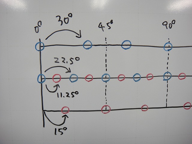
From here on, I'll color the right rim holes blue and the left rim holes red.
The hub holes are also blue for the right flange and red for the left flange.

The reason the phase doesn't align is, of course, that the hole spacing differs between rim and hub.
In a straight-line expansion diagram, the horizontal axis length equals the angle itself.
When I draw that, it looks like the diagram above, and clearly the phases won't match.

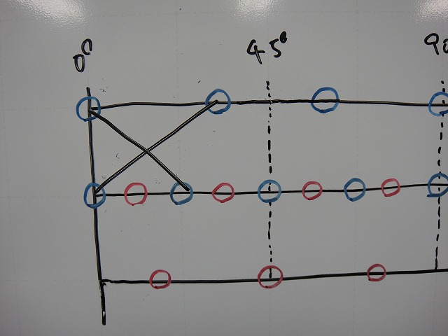
Let me try tangent lacing once more.

The next hub hole would make the spoke extremely slanted,
so let me try skipping one hole here.
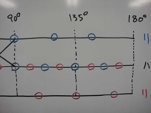
I'll mark the resting holes with a double circle.

Then what remains is 3 hub holes to 2 rim holes.

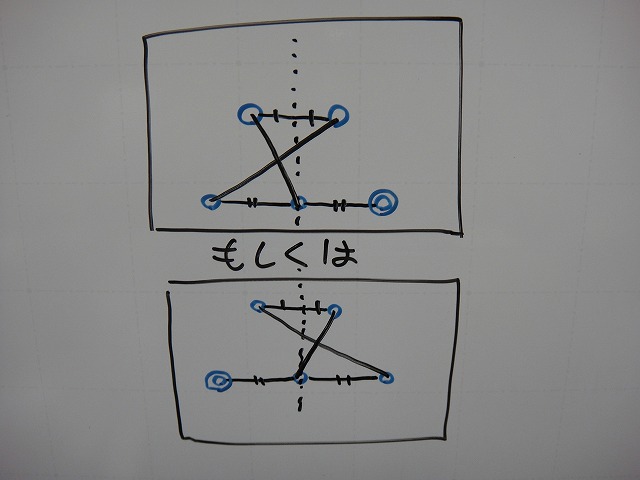
In this case, whichever way you go through,
the spoke length differences are the same and the crossings are mirror symmetric.

↑I went through this way.

The two crossings from before are also mirror symmetric.
If I call them "porcupine-direction length → anti-porcupine-direction length,"
the spoke lengths are B and A, then A and B.

When I apply that to the earlier crossing as well, it becomes C and D.
At this point, there are 4 different spoke lengths on one flange,
but if I were to tension and true the rim on it,
the hub would rotate and twist rather than having the spokes themselves
with lengths A, B, C, D assemble as-is.
(Within what the spoke lengths allow, of course.)
I've numbered the hub holes from one end.
The resting holes are 3 and 6.

Pulling the middle of a straight-line expansion diagram to cycle it
is the same as rotating only the hub side in a radian-sense diagram.

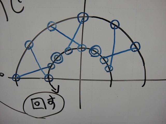
When I rotate this,

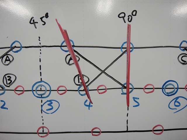
the amount I rotate is
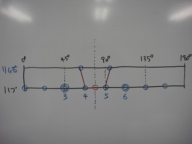
"until the angles of the zero-cross spokes from holes 4 and 5 become mirror symmetric."

Right there.

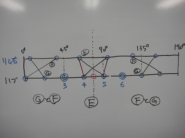
From that position, I made 3 tangent-laced crossings.
Only the center crossing has equal spoke lengths on both sides.
This is probably the best-balanced lacing pattern for a 32H hub and 24H rim
with equal spokes on both sides.

There's first a crossing of length E spokes where there's no spoke length difference,

next to which on each side is a resting hole,

and then F and G spoke crossings.

I've simplified this to 2-cross lacing for illustration,
but if you can calculate the spoke lengths, you could certainly do 4-cross lacing, etc.
So would I actually build it this way? The answer is absolutely not.
"I won't build a wheel where the spoke trajectory itself in zero-cross lacing,
or the extension of a line connecting the final crossing and hub center in tangent lacing,
deviates from the radial line."
This is a rule I have that's quite firm.
The "actual harm from building such a wheel" that I didn't mention earlier
is that the spokes loosen abnormally easily.
Even if I were to hold them with a strong threadlocker,
the spoke balance issue remains.

In a tangent-laced wheel with no angle mismatch,
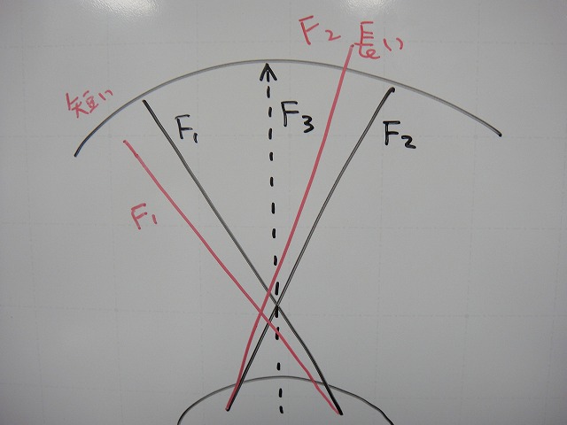
the resultant force F3 of the porcupine-direction spoke F1 and anti-porcupine-direction spoke F2
lies on the radial line.
(As I'll write later, if the spokes each have different thicknesses, this doesn't apply.)

When the phase between hub and rim holes shifts and the spoke angle changes,
you end up doing tangent lacing with spokes of different lengths.

Also, because F3's direction deviates from the radial line, it's NG.

So can you build a 32H hub and 24H rim keeping the spoke tension direction on the radial line?
Well, actually you can.

↑In that case, you can't fix the phase between hub and rim holes at the 0° position like this.

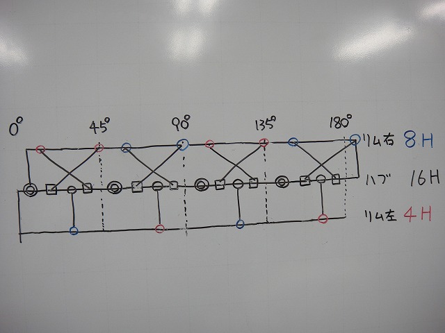
I changed the 24H rim's 180° worth of rim holes—12H for left and right—
from right-left-right-left-right-left-right-left-right-left-right-left
to right-right-left-right-right-left-right-right-left-right-right-left.
The rim hole pattern information is preserved as color-coding.
I changed it from 6H right / 6H left to 8H right / 4H left,

and then position the hub holes so that the zero-cross lacing from the left 4H becomes radial lacing.

The remaining half of the left flange becomes resting holes.
I'll add them with double circles.

Next, I've added 8H worth of right flange holes.
I'm drawing them as squares for easy distinction.
Since this is 8H rim to 8H hub, we use all of them.

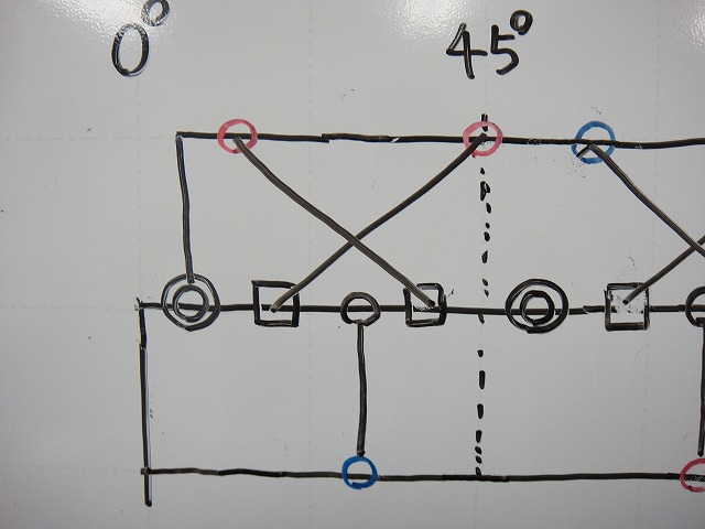
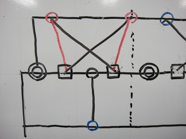
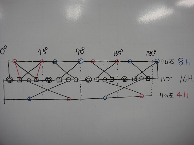
I've drawn 3 pairs of the 4 tangent-laced pairs.
The remaining pair is

brought here with a phase shift.
So what this means is that you can do it with 2:1 lacing.

The resultant force of this tangent-laced spoke's tension direction
lies on the radial line, so it doesn't violate the prohibition I mentioned earlier.

Zero-cross lacing is different.
It deviates from the radial line, so it's NG.
But since the spoke lengths are all the same on a single flange,
the spoke balance isn't as bad as the G-F-E-E-F-G tangent-laced pattern from earlier.

For 2:1 lacing with anti-freewheel side radial lacing,
on a super high-low flange Fulcrum, spoke tension (to clarify, it's the second spoke tension)
is roughly 100:100 between freewheel side and anti-freewheel side.
Even with Evolite hubs or Leaf hubs, it's around 100:90 or so.
So with 2:1 lacing doing tangent on both sides
or freewheel side radial / anti-freewheel side tangent, etc., is actually not good.
I have the idea that "the total spoke tension on the anti-freewheel side is shared among the hole count,"
and if that is halved, spoke tension doesn't double, but the load increases substantially.
Since I can't explain the merit of tangent lacing on the non-ratio flange
over radial lacing in terms of a raising of tension,
I use radial lacing on the anti-freewheel side when forced into 2:1 lacing.
It's not asked to handle torsional rigidity as much as the freewheel side,
and depending on hub dimensions or the degree of left-right different-spoke lacing,
I can't explain the merit above the demerit of reversed left-right tensions,
so I don't do patterns like what's shown in the diagram above—
"2:1 lacing with anti-freewheel side also tangent laced."
I'm not saying this without doing it; I say this because I tried it and it didn't work.
this blog's article comes up first (→here).
Looks like I'll have to work this out myself.
Maybe this article will be the top result in the near future.
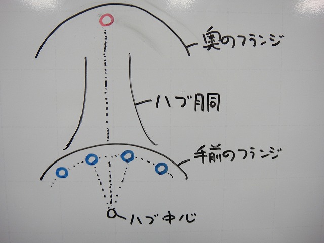
For a normal hub without pair-spoke phasing,
the left and right flange holes are offset by 360°/(left and right hole count)°.
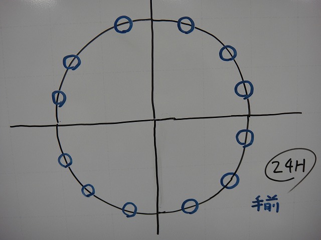
Whether it's the hub or rim, but let's say 24H—
when we skip one hole on one side of the hub flange or on the rim,
the hole positions look like the diagram above.

Adding the holes on the other side looks like this.
If I draw two concentric circles of different radii, make the larger one the rim and the smaller one the hub,
mark the hole positions on each, and connect the rim holes to the hub holes with lines (←spokes),
that becomes a wheel design diagram.
But if I try to build a 32H hub with a 24H rim using the same number of spokes on each side,
phase mismatch occurs.
To explain that phase mismatch in an intuitively clear way, my case
is that I find a diagram with the arc expanded into a straight line easier to understand
than a "radian sense" style circle. So I'll explain based on that from here on.
This is literally the diagram I imagine in my head when dealing with different hole counts between hub and rim.
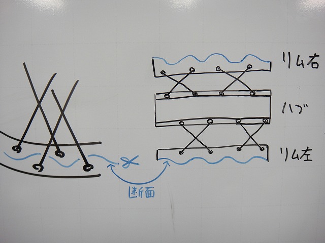
There are two types of straight-line expansion diagrams of a wheel arc.
One is the "rim-hub-rim type" expansion diagram, where you divide the rim following the hole pattern
(or alternating if there's no pattern) and lay it alongside the hub.
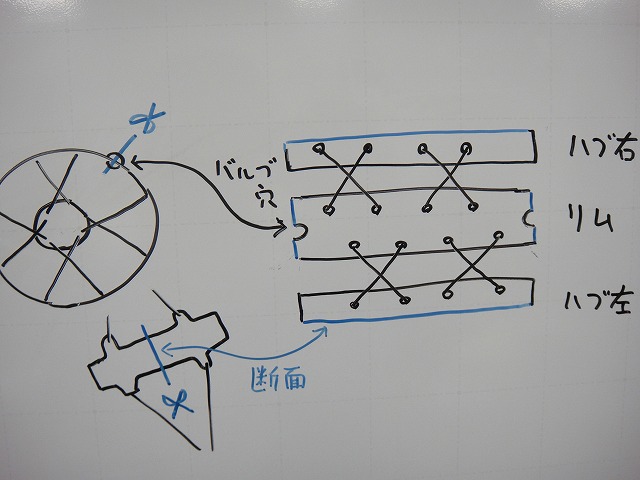
The other is the "hub-rim-hub type" expansion diagram, where you cut the hub shell in the middle and split the rim
to lay it flat. Think of it like cutting a clincher tire and spreading it out like eel kabayaki (grilled eel)—
that's what we're doing to the wheel here.
I'll use this type today.
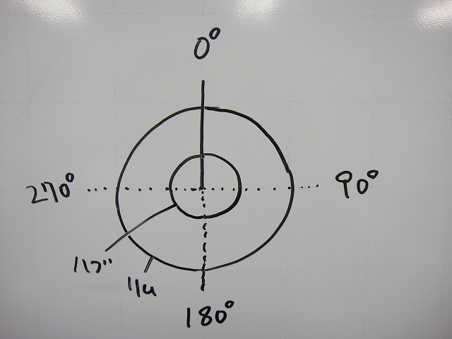
Normally, 0° in radians is on the X-axis, at 3 o'clock on a clock face,
but in my "radian sense," the 0° position isn't fixed.
It's wherever makes the phase easiest to imagine at the time.
In the diagram above, it's at 12 o'clock.
The clockwise direction is also opposite to true radian convention.

I'll cut out just 90° from here.
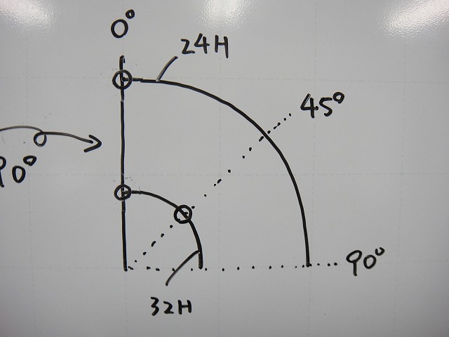
I'll draw both the rim hole and hub hole on the 0° line.
This time it's a 24H rim and 32H hub, but
the 32H hub has 4H in each 90° of flange, which is even,
so there will be holes on the 45° line as well.
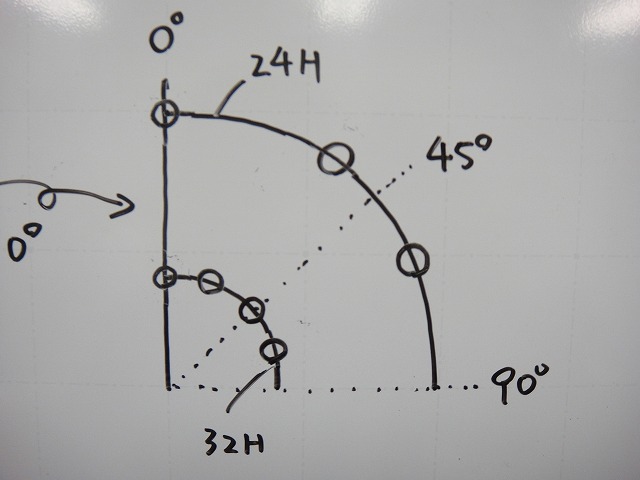
I've drawn all the hub holes and rim holes for the 90° section.
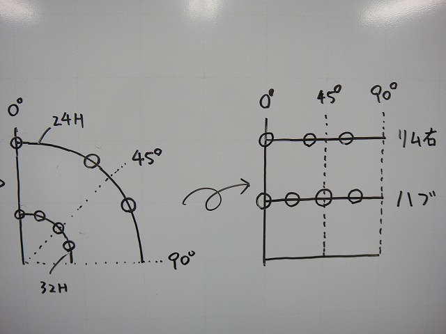
When I convert this to a straight-line expansion diagram, it looks like this.

Further, I've added the hub phase on the far side and the adjacent rim hole phase.
With a 24H rim, there are 3 holes in the 90° section,
and since that's odd, you can't do tangent lacing,
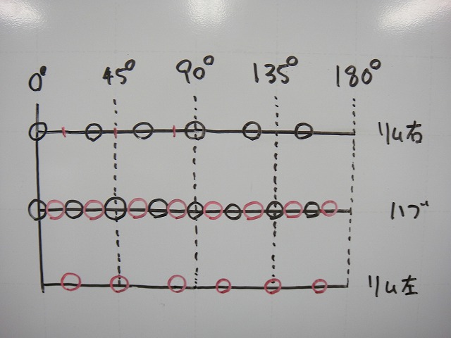
so I extended the diagram to 180° to make it 6 holes.
Basically, I just repeated the 90° diagram twice side by side.
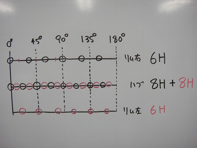
The 180° section has 16H total hub holes between left and right,
which means 8H on the right and 8H on the left if we use equal spokes on both sides.
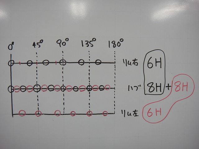
The question today is whether you can do tangent lacing with 8H on one hub side and 6H on one rim side
without causing phase mismatch.
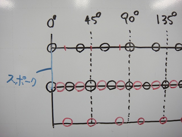
First, let me try zero-cross lacing at the 0° point.
"Zero-cross lacing ≠ radial lacing."
If the trajectory of a zero-cross lacing spoke is not on a straight radial line
(below: radial line) extending from the hub center,
I don't call it radial lacing.
This spoke is perpendicular to the horizontal axis, so it is "radial lacing."
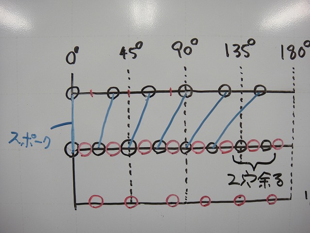
I've drawn 6H on one rim side from the edge using zero-cross lacing,
without skipping holes or anything.
The other 5 spokes besides the one just drawn are zero-cross laced,
but they don't extend along the radial line, so they are not radial laced.
This is the "zero-cross but not radial lacing" case.
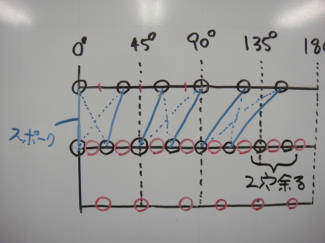
When I try tangent lacing the 6H rim holes in this phase,
the spoke lengths of the finally crossing spokes are different from each other.
This is a serious problem. I'll discuss the actual harm later.
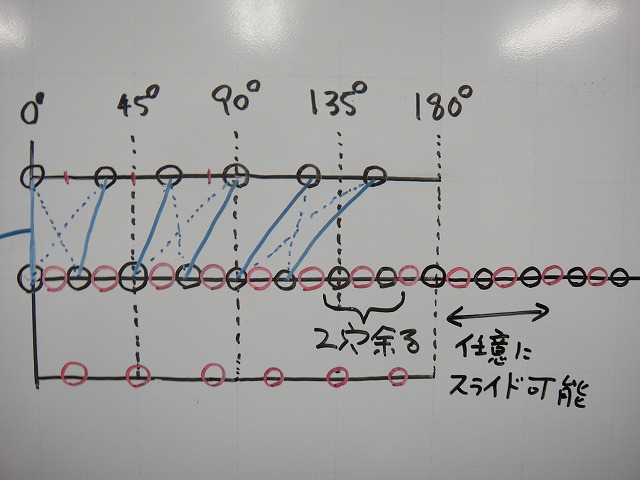
Whether it's rim-hub-rim type or hub-rim-hub type,
the middle line cycles, so if needed
you can shift it arbitrarily.
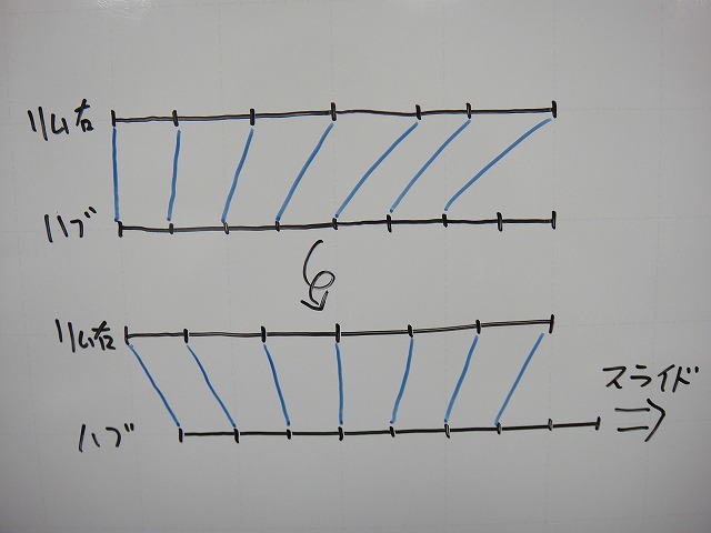
↑You can shift it like this.

The same diagram, but redrawn with more horizontal space.
From here on, I'll color the right rim holes blue and the left rim holes red.
The hub holes are also blue for the right flange and red for the left flange.
The reason the phase doesn't align is, of course, that the hole spacing differs between rim and hub.
In a straight-line expansion diagram, the horizontal axis length equals the angle itself.
When I draw that, it looks like the diagram above, and clearly the phases won't match.
Let me try tangent lacing once more.

The next hub hole would make the spoke extremely slanted,
so let me try skipping one hole here.
I'll mark the resting holes with a double circle.
Then what remains is 3 hub holes to 2 rim holes.
In this case, whichever way you go through,
the spoke length differences are the same and the crossings are mirror symmetric.
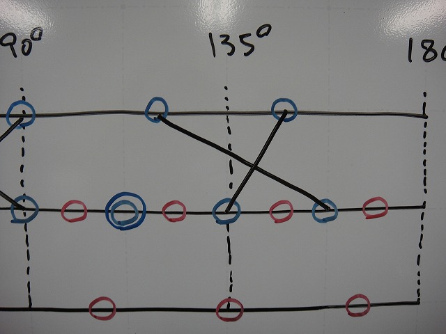
↑I went through this way.
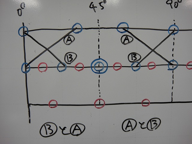
The two crossings from before are also mirror symmetric.
If I call them "porcupine-direction length → anti-porcupine-direction length,"
the spoke lengths are B and A, then A and B.
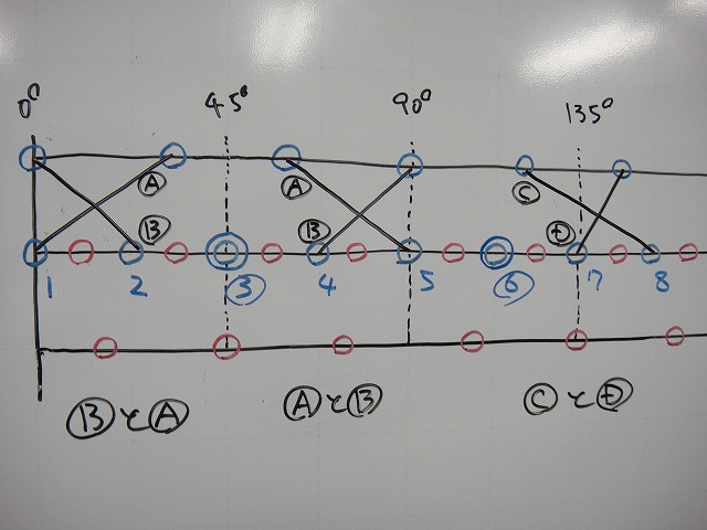
When I apply that to the earlier crossing as well, it becomes C and D.
At this point, there are 4 different spoke lengths on one flange,
but if I were to tension and true the rim on it,
the hub would rotate and twist rather than having the spokes themselves
with lengths A, B, C, D assemble as-is.
(Within what the spoke lengths allow, of course.)
I've numbered the hub holes from one end.
The resting holes are 3 and 6.
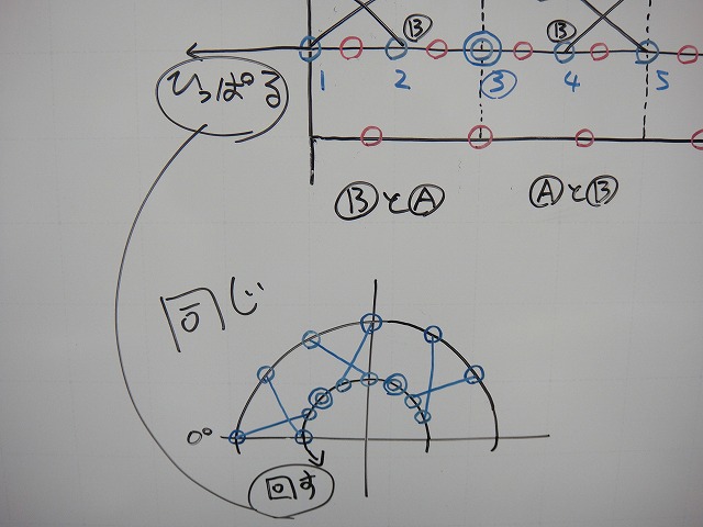
Pulling the middle of a straight-line expansion diagram to cycle it
is the same as rotating only the hub side in a radian-sense diagram.
When I rotate this,
the amount I rotate is
"until the angles of the zero-cross spokes from holes 4 and 5 become mirror symmetric."
Right there.
From that position, I made 3 tangent-laced crossings.
Only the center crossing has equal spoke lengths on both sides.
This is probably the best-balanced lacing pattern for a 32H hub and 24H rim
with equal spokes on both sides.
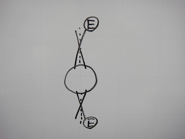
There's first a crossing of length E spokes where there's no spoke length difference,
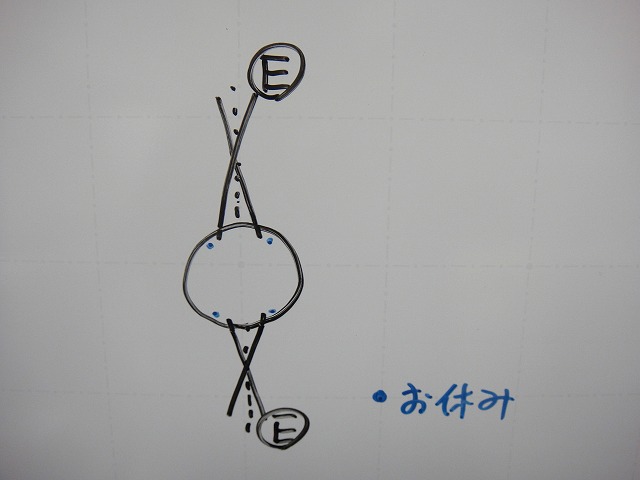
next to which on each side is a resting hole,

and then F and G spoke crossings.
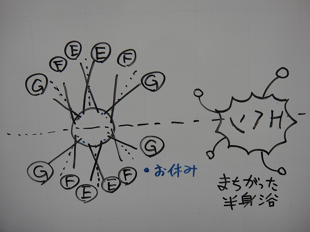
I've simplified this to 2-cross lacing for illustration,
but if you can calculate the spoke lengths, you could certainly do 4-cross lacing, etc.
So would I actually build it this way? The answer is absolutely not.
"I won't build a wheel where the spoke trajectory itself in zero-cross lacing,
or the extension of a line connecting the final crossing and hub center in tangent lacing,
deviates from the radial line."
This is a rule I have that's quite firm.
The "actual harm from building such a wheel" that I didn't mention earlier
is that the spokes loosen abnormally easily.
Even if I were to hold them with a strong threadlocker,
the spoke balance issue remains.
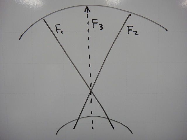
In a tangent-laced wheel with no angle mismatch,
the resultant force F3 of the porcupine-direction spoke F1 and anti-porcupine-direction spoke F2
lies on the radial line.
(As I'll write later, if the spokes each have different thicknesses, this doesn't apply.)
When the phase between hub and rim holes shifts and the spoke angle changes,
you end up doing tangent lacing with spokes of different lengths.
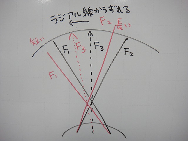
Also, because F3's direction deviates from the radial line, it's NG.
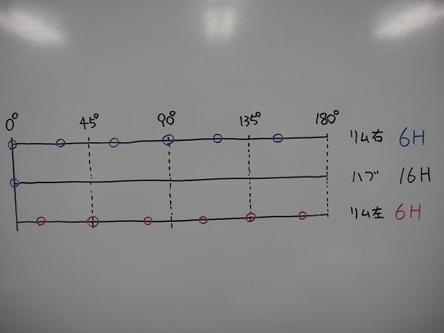
So can you build a 32H hub and 24H rim keeping the spoke tension direction on the radial line?
Well, actually you can.
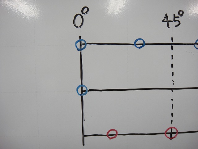
↑In that case, you can't fix the phase between hub and rim holes at the 0° position like this.
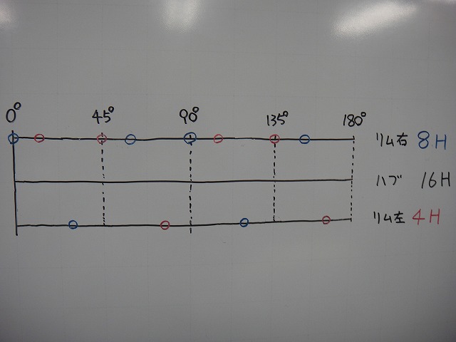
I changed the 24H rim's 180° worth of rim holes—12H for left and right—
from right-left-right-left-right-left-right-left-right-left-right-left
to right-right-left-right-right-left-right-right-left-right-right-left.
The rim hole pattern information is preserved as color-coding.
I changed it from 6H right / 6H left to 8H right / 4H left,
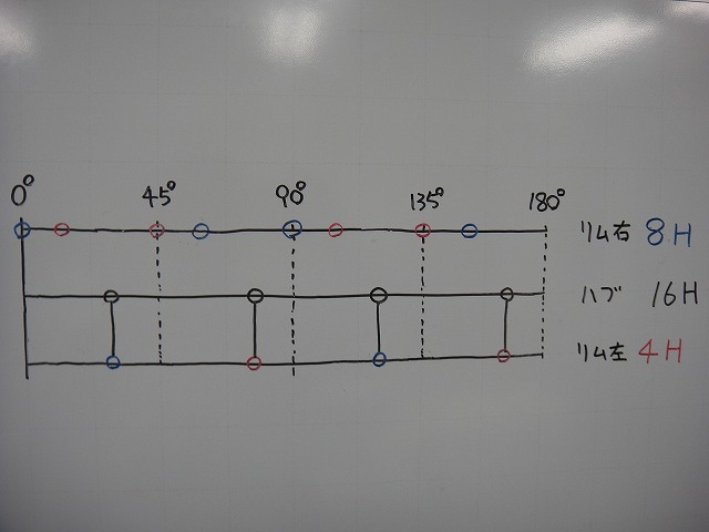
and then position the hub holes so that the zero-cross lacing from the left 4H becomes radial lacing.
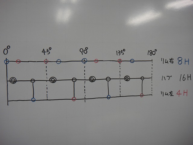
The remaining half of the left flange becomes resting holes.
I'll add them with double circles.

Next, I've added 8H worth of right flange holes.
I'm drawing them as squares for easy distinction.
Since this is 8H rim to 8H hub, we use all of them.
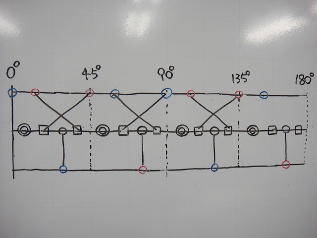
I've drawn 3 pairs of the 4 tangent-laced pairs.
The remaining pair is
brought here with a phase shift.
So what this means is that you can do it with 2:1 lacing.
The resultant force of this tangent-laced spoke's tension direction
lies on the radial line, so it doesn't violate the prohibition I mentioned earlier.
Zero-cross lacing is different.
It deviates from the radial line, so it's NG.
But since the spoke lengths are all the same on a single flange,
the spoke balance isn't as bad as the G-F-E-E-F-G tangent-laced pattern from earlier.
For 2:1 lacing with anti-freewheel side radial lacing,
on a super high-low flange Fulcrum, spoke tension (to clarify, it's the second spoke tension)
is roughly 100:100 between freewheel side and anti-freewheel side.
Even with Evolite hubs or Leaf hubs, it's around 100:90 or so.
So with 2:1 lacing doing tangent on both sides
or freewheel side radial / anti-freewheel side tangent, etc., is actually not good.
I have the idea that "the total spoke tension on the anti-freewheel side is shared among the hole count,"
and if that is halved, spoke tension doesn't double, but the load increases substantially.
Since I can't explain the merit of tangent lacing on the non-ratio flange
over radial lacing in terms of a raising of tension,
I use radial lacing on the anti-freewheel side when forced into 2:1 lacing.
It's not asked to handle torsional rigidity as much as the freewheel side,
and depending on hub dimensions or the degree of left-right different-spoke lacing,
I can't explain the merit above the demerit of reversed left-right tensions,
so I don't do patterns like what's shown in the diagram above—
"2:1 lacing with anti-freewheel side also tangent laced."
I'm not saying this without doing it; I say this because I tried it and it didn't work.
Original Japanese post: のむラボ日記 #1086