The other day, I wrote about hand-built wheels with 2:1 lacing on the freewheel side
having an extremely high risk of spoke neck breakage on the non-freewheel side,
so we don't do it for wheels we're selling—and I received several comments about that.
"With 2:1 lacing on 24H, the 8 spokes on the NDS side bear a heavy load and tend to break,
but what about 4:3 lacing on 28H?
With 16 spokes on one side and 12 on the other, it seems like it could work with a 32H hub…"
"With hand-built 2:1, the spokes on the side with fewer are prone to failure, you say.
Sure, it might look good statically, but dynamically—say, under the impact of cornering—
can just half the number of spokes really handle that load? It sounds tough.
So what about hand-built 4:3 lacing? That's my question.
For example, with a 32H hub and 28H rim, building 16:12, do you think that makes sense?"
I've excerpted just two comments, but they're from different people.
16 + 12 = 28, right?
Whether wheels like this can be built without problems,
or whether they can be built conditionally,
or whether it's basically impossible—
there's a simple method to judge this.
That's what I'm writing about today.

As I wrote somewhere on this blog before,
just draw a flat pattern diagram of the wheel (→here).
Actually, what I'm about to write overlaps quite a bit with that,
but that's fine.
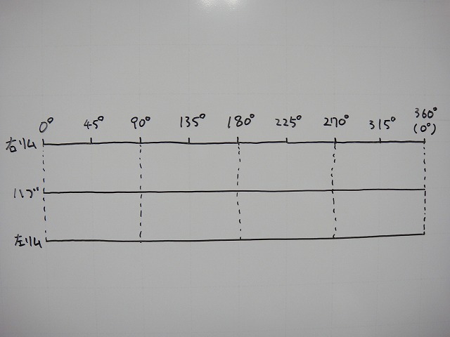
This time I'm using a 32H hub and 28H rim,
and I'll draw the diagram in rim-hub-rim format.
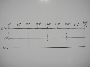
From here on, I'll refer to the freewheel side as right and the non-freewheel side as left.
Let's think about a rear wheel with 16H on the right and 12H on the left.
16:12 reduces to 4:3, but when you reduce it,
you sometimes "cut through the one unit of the pattern"
and "the one unit of the pattern and the smallest divisor aren't necessarily the same"—
so it's better to write it using the actual spoke counts (16:12 in this case).
I'll touch on "pattern" later.
I'll also write about a Colima 20H rear wheel later,
but that 12:8 shouldn't be written as 3:2 either.
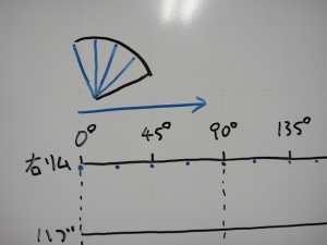
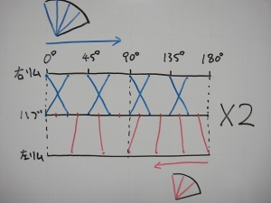
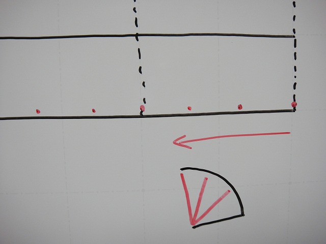
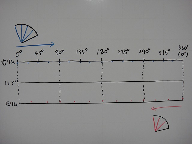
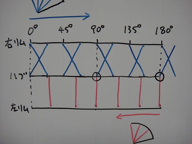
I'll draw the rim-side holes for the 16 right-side spokes.
Four holes per 90° phase.
Similarly, I'll draw the rim-side holes for the 12 left-side spokes from the opposite side.
Three holes per 90° phase.

Done drawing.
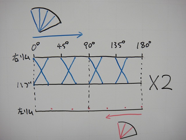
I'll draw the right side in tangential lacing.
To keep the diagram from getting too messy, I'll draw it as 2-cross lacing.

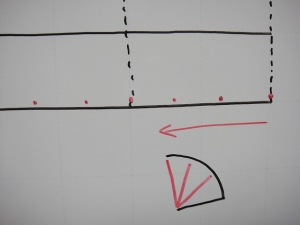
The diagram was getting long, so I cut it short.
This wheel repeats the 180° phase pattern twice.
This pattern is one unit of repetition.
I decided to draw only that part.

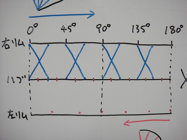
I've added the holes for the left-side spokes at the hub.
In this state, we have 8H at the hub and 6H at the rim per repetition unit, so…
You'd be selecting 6 out of 8,
and even with 0-cross lacing,
you won't get radial lacing (= spokes on radial lines).
Phase offset occurs.
Since there's no phase offset with a 32H hub and 24H rim,
I can somewhat imagine it happening with a 28H rim,
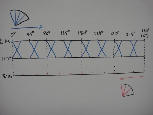
but here's what the diagram looks like:
This doesn't meet the "can be built without problems" category I mentioned earlier.

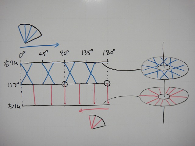
Next, to satisfy "can be built conditionally,"
let's allow the hub-side holes to be drilled at a special phase.
Pull a spoke straight from the rim-side hole and decide the hub-side hole afterward.
In the diagram I drew it with radial lacing,
but since the number of left spokes in one repetition unit is even, tangential lacing would be OK too.
I've drawn two circles on the hub line,
and since spokes overlap here at the hub, they must also overlap at the rim.
This means left and right spokes come to the same phase on the rim.
There's a wheelmaker called XAERO that makes wheels with flat-topped rims
where left and right spokes sit side-by-side in complete pair-spoke configuration,
but rims where spokes can be built even when they come to the same phase on the rim are quite rare.
Especially with aero rims.
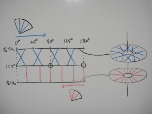
The reason I drew the diagram in rim-hub-rim format this time is for this very reason—
when you turn the left and right rims back into circles, it looks like this.

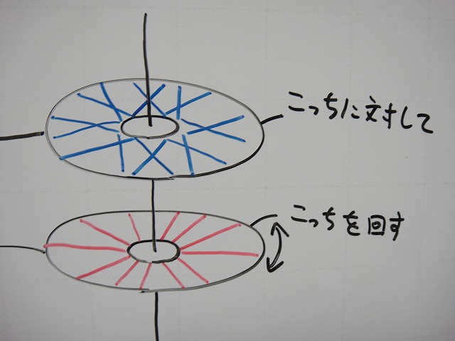
For these left and right rims,
I'll rotate one relative to the other
to find just the right position where spokes don't come to the same phase on the rim.
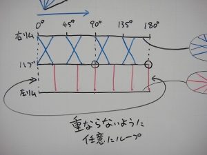
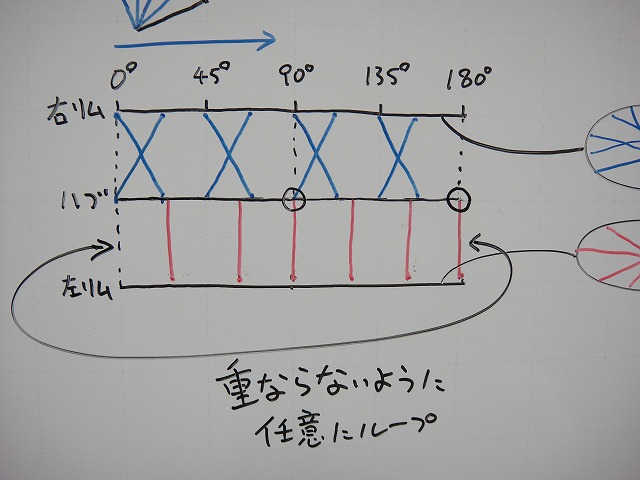
When you express that in a flat pattern diagram,
it's equivalent to arbitrarily looping one rim's line.
So if you're doing 16:12 lacing with a 32H hub and 28H rim,
if the hub-side holes can be drilled arbitrarily, you can build it without phase offset;
with a normally spaced flange hole hub, it's impossible.
By the way, from among the comments I introduced,
the person who made the second comment has sent another comment.
"I'm the one who commented earlier. Sorry for the double post.
Now that I think about it, the phase would be off, so the rim would need to be 32H too.
I haven't actually built a wheel yet, so I don't fully understand,
but I thought of 4:3 so I wrote about it. What do you think?"
That's what they said.
To notice phase offset without ever having built a wheel…!
You're no ordinary person!
Now, about 4:3 lacing—
8:6 at 14H,
12:9 at 21H,
16:12 at 28H,
20:15 at 35H.
Adding more spokes beyond that just makes things heavier, so that's about the practical range.
Everything except 28H requires rims with non-standard hole counts.
Only at 28H can you make a wheel if you prepare a special hub,
but given the spoke counts of current mass-produced wheels,
I can't find weight advantages,
so if a manufacturer tried it, I'd guess it would get scrapped.
If anyone else has thought of asymmetrical lacing ratios,
try drawing a flat pattern diagram using the method I described earlier.
I'm pretty sure there aren't any practical left-right ratios that
wheelmakers or I haven't already thought of.

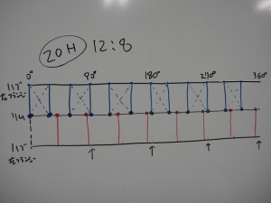
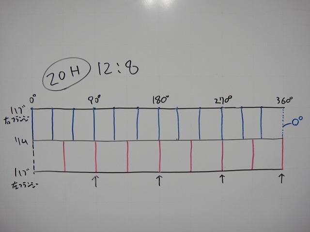
Next, about Colima's 12:8, 20H rear wheel.
I drew the pattern diagram the same way as before—right 12H, left 8H.
This time it's in hub-rim-hub format.
The result is that at four locations every 90° phase,
the spokes clash (the parts with the up arrows).
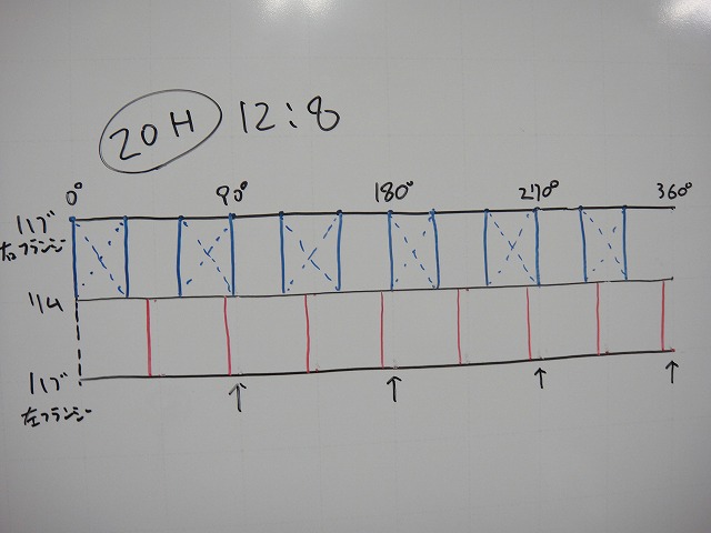
I drew the right side in radial lacing anyway.
To avoid spoke overlap, I'll shift the phase of the left-side spokes
to an appropriate position.
Rather than loop, I'll shift slightly to the left.
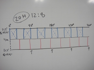
Shifted.
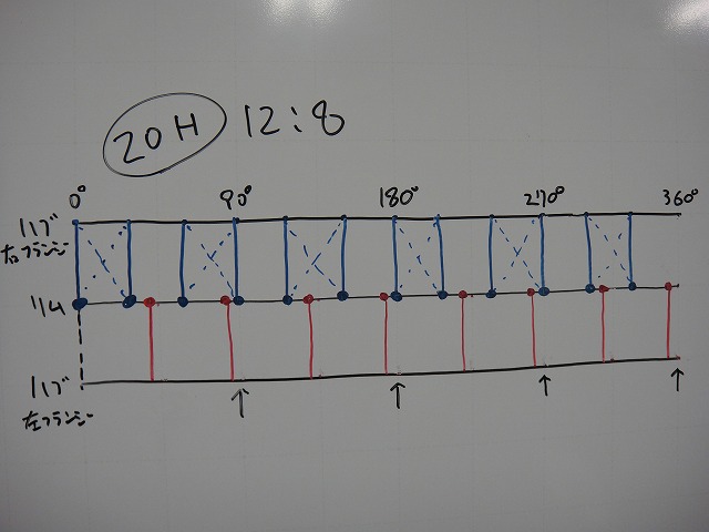
In this diagram, the repetition unit isn't 90° four times, but 180° twice.
(I added the tangential lacing in blue dashed lines.
Looking at the positional relationship from the left edge—the 4 left spokes and
where they cross with the right tangential lacing—
it goes "between crossings, in crossing, in crossing, between crossings").
The right side almost never uses radial lacing,
but to use tangential lacing,
you need an even number of spokes on each flange,
and if you reduce 12:8 20H to 3:2,
the right side becomes 3H and you cut through the repetition unit.
That's why I wrote earlier that "it's better not to reduce".
Now, for Colima's 12:8 20H rear wheel,
if Colima's phase offset were hypothetically the same as this,

right rightleftrightleftright rightleftrightleft would be one unit repeating twice.
I drew the diagram in hub-rim-hub format to make this clearer.
If you look at just the rightleft hole pattern, it looks like right rightleftrightleft repeating four times,
but since the spacing of the rim-side holes is different, the same pattern is every 180°.
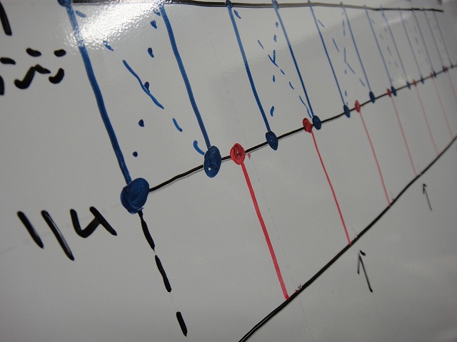
This "consecutive holes on the same side" situation
is a major weakness of asymmetrical lacing…

This kind of situation always shows up.
So whether it's Fulcrum or other asymmetrical lacing wheels,
they're very lenient about radial runout tolerance.
They have radial runout you'd never see on a normal hand-built wheel,
but it's absorbed by tire deformation at the contact patch,
so it's considered acceptable.
Even when I use wheels like this, the radial runout isn't noticeable.
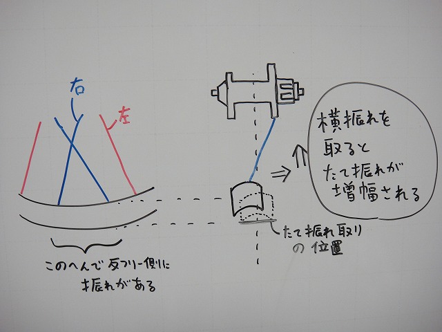
When I normally check Fulcrum wheels and others like them,
I focus on the area around the left spokes,
and even then I work at keeping radial runout minimal while taking out lateral runout.
And with Campagnolo's G3, at the points where
three left spokes pull together,
the inner rim distorts considerably, so
G3 wheels with 21H (7 repetitions)
end up with a rim shape that's something like a regular heptagon plus three circles divided by four.
That's no exaggeration whatsoever.
On Campagnolo and Fulcrum aluminum rims,
the areas except around the nipple base look like they're "machined away,"
but I actually think they're "raised up" to
suppress inner rim distortion caused by spoke tension.

↑If I had a spoke (shown in red dashed line),
I could loosen the nipple and push outward to reduce both radial and lateral runout at the same time,
but…
The reason we don't do asymmetrical lacing on hand-built wheels is
that within realistic limits, there are no spoke combinations that don't cause phase offset
except 2:1 lacing with a 32H hub and 24H rim
(where hub hole overage is OK but rim hole overage is NG),
and then there's the spoke breakage issue and the radial runout tolerance issue.
Though the correction of spoke tension difference between left and right is absolutely superior…
having an extremely high risk of spoke neck breakage on the non-freewheel side,
so we don't do it for wheels we're selling—and I received several comments about that.
"With 2:1 lacing on 24H, the 8 spokes on the NDS side bear a heavy load and tend to break,
but what about 4:3 lacing on 28H?
With 16 spokes on one side and 12 on the other, it seems like it could work with a 32H hub…"
"With hand-built 2:1, the spokes on the side with fewer are prone to failure, you say.
Sure, it might look good statically, but dynamically—say, under the impact of cornering—
can just half the number of spokes really handle that load? It sounds tough.
So what about hand-built 4:3 lacing? That's my question.
For example, with a 32H hub and 28H rim, building 16:12, do you think that makes sense?"
I've excerpted just two comments, but they're from different people.
16 + 12 = 28, right?
Whether wheels like this can be built without problems,
or whether they can be built conditionally,
or whether it's basically impossible—
there's a simple method to judge this.
That's what I'm writing about today.
As I wrote somewhere on this blog before,
just draw a flat pattern diagram of the wheel (→here).
Actually, what I'm about to write overlaps quite a bit with that,
but that's fine.
This time I'm using a 32H hub and 28H rim,
and I'll draw the diagram in rim-hub-rim format.
From here on, I'll refer to the freewheel side as right and the non-freewheel side as left.
Let's think about a rear wheel with 16H on the right and 12H on the left.
16:12 reduces to 4:3, but when you reduce it,
you sometimes "cut through the one unit of the pattern"
and "the one unit of the pattern and the smallest divisor aren't necessarily the same"—
so it's better to write it using the actual spoke counts (16:12 in this case).
I'll touch on "pattern" later.
I'll also write about a Colima 20H rear wheel later,
but that 12:8 shouldn't be written as 3:2 either.

I'll draw the rim-side holes for the 16 right-side spokes.
Four holes per 90° phase.
Similarly, I'll draw the rim-side holes for the 12 left-side spokes from the opposite side.
Three holes per 90° phase.
Done drawing.

I'll draw the right side in tangential lacing.
To keep the diagram from getting too messy, I'll draw it as 2-cross lacing.
The diagram was getting long, so I cut it short.
This wheel repeats the 180° phase pattern twice.
This pattern is one unit of repetition.
I decided to draw only that part.
I've added the holes for the left-side spokes at the hub.
In this state, we have 8H at the hub and 6H at the rim per repetition unit, so…

You'd be selecting 6 out of 8,
and even with 0-cross lacing,
you won't get radial lacing (= spokes on radial lines).
Phase offset occurs.
Since there's no phase offset with a 32H hub and 24H rim,
I can somewhat imagine it happening with a 28H rim,
but here's what the diagram looks like:
This doesn't meet the "can be built without problems" category I mentioned earlier.
Next, to satisfy "can be built conditionally,"
let's allow the hub-side holes to be drilled at a special phase.
Pull a spoke straight from the rim-side hole and decide the hub-side hole afterward.
In the diagram I drew it with radial lacing,
but since the number of left spokes in one repetition unit is even, tangential lacing would be OK too.
I've drawn two circles on the hub line,
and since spokes overlap here at the hub, they must also overlap at the rim.
This means left and right spokes come to the same phase on the rim.
There's a wheelmaker called XAERO that makes wheels with flat-topped rims
where left and right spokes sit side-by-side in complete pair-spoke configuration,
but rims where spokes can be built even when they come to the same phase on the rim are quite rare.
Especially with aero rims.
The reason I drew the diagram in rim-hub-rim format this time is for this very reason—
when you turn the left and right rims back into circles, it looks like this.
For these left and right rims,
I'll rotate one relative to the other
to find just the right position where spokes don't come to the same phase on the rim.
When you express that in a flat pattern diagram,
it's equivalent to arbitrarily looping one rim's line.
So if you're doing 16:12 lacing with a 32H hub and 28H rim,
if the hub-side holes can be drilled arbitrarily, you can build it without phase offset;
with a normally spaced flange hole hub, it's impossible.
By the way, from among the comments I introduced,
the person who made the second comment has sent another comment.
"I'm the one who commented earlier. Sorry for the double post.
Now that I think about it, the phase would be off, so the rim would need to be 32H too.
I haven't actually built a wheel yet, so I don't fully understand,
but I thought of 4:3 so I wrote about it. What do you think?"
That's what they said.
To notice phase offset without ever having built a wheel…!
You're no ordinary person!
Now, about 4:3 lacing—
8:6 at 14H,
12:9 at 21H,
16:12 at 28H,
20:15 at 35H.
Adding more spokes beyond that just makes things heavier, so that's about the practical range.
Everything except 28H requires rims with non-standard hole counts.
Only at 28H can you make a wheel if you prepare a special hub,
but given the spoke counts of current mass-produced wheels,
I can't find weight advantages,
so if a manufacturer tried it, I'd guess it would get scrapped.
If anyone else has thought of asymmetrical lacing ratios,
try drawing a flat pattern diagram using the method I described earlier.
I'm pretty sure there aren't any practical left-right ratios that
wheelmakers or I haven't already thought of.
Next, about Colima's 12:8, 20H rear wheel.
I drew the pattern diagram the same way as before—right 12H, left 8H.
This time it's in hub-rim-hub format.
The result is that at four locations every 90° phase,
the spokes clash (the parts with the up arrows).
I drew the right side in radial lacing anyway.
To avoid spoke overlap, I'll shift the phase of the left-side spokes
to an appropriate position.
Rather than loop, I'll shift slightly to the left.
Shifted.
In this diagram, the repetition unit isn't 90° four times, but 180° twice.
(I added the tangential lacing in blue dashed lines.
Looking at the positional relationship from the left edge—the 4 left spokes and
where they cross with the right tangential lacing—
it goes "between crossings, in crossing, in crossing, between crossings").
The right side almost never uses radial lacing,
but to use tangential lacing,
you need an even number of spokes on each flange,
and if you reduce 12:8 20H to 3:2,
the right side becomes 3H and you cut through the repetition unit.
That's why I wrote earlier that "it's better not to reduce".
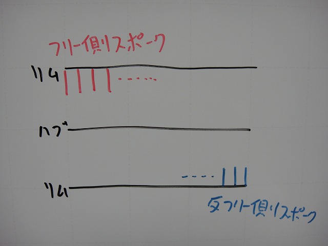
Now, for Colima's 12:8 20H rear wheel,
if Colima's phase offset were hypothetically the same as this,
right rightleftrightleftright rightleftrightleft would be one unit repeating twice.
I drew the diagram in hub-rim-hub format to make this clearer.
If you look at just the rightleft hole pattern, it looks like right rightleftrightleft repeating four times,
but since the spacing of the rim-side holes is different, the same pattern is every 180°.
This "consecutive holes on the same side" situation
is a major weakness of asymmetrical lacing…
This kind of situation always shows up.
So whether it's Fulcrum or other asymmetrical lacing wheels,
they're very lenient about radial runout tolerance.
They have radial runout you'd never see on a normal hand-built wheel,
but it's absorbed by tire deformation at the contact patch,
so it's considered acceptable.
Even when I use wheels like this, the radial runout isn't noticeable.
When I normally check Fulcrum wheels and others like them,
I focus on the area around the left spokes,
and even then I work at keeping radial runout minimal while taking out lateral runout.
And with Campagnolo's G3, at the points where
three left spokes pull together,
the inner rim distorts considerably, so
G3 wheels with 21H (7 repetitions)
end up with a rim shape that's something like a regular heptagon plus three circles divided by four.
That's no exaggeration whatsoever.

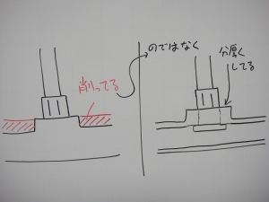
On Campagnolo and Fulcrum aluminum rims,
the areas except around the nipple base look like they're "machined away,"
but I actually think they're "raised up" to
suppress inner rim distortion caused by spoke tension.
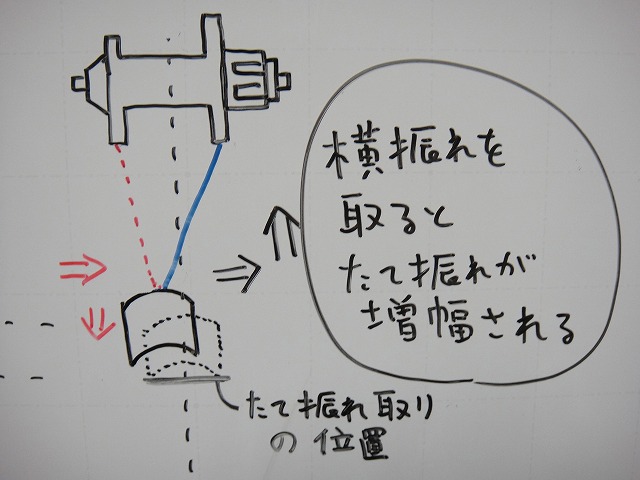
↑If I had a spoke (shown in red dashed line),
I could loosen the nipple and push outward to reduce both radial and lateral runout at the same time,
but…
The reason we don't do asymmetrical lacing on hand-built wheels is
that within realistic limits, there are no spoke combinations that don't cause phase offset
except 2:1 lacing with a 32H hub and 24H rim
(where hub hole overage is OK but rim hole overage is NG),
and then there's the spoke breakage issue and the radial runout tolerance issue.
Though the correction of spoke tension difference between left and right is absolutely superior…