The drill is screaming!
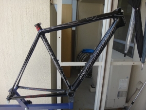
Not from a regular customer, but I received a Super Six EVO frame designed for Shimano Di2 (electronic drivetrain) from a former colleague in the bike industry.
He wants to build it up with mechanical drivetrain components and is asking me to install cable bosses (cable guides).
I told him, "If you're still in the industry, even as a former colleague, do it yourself,"
but he said that's impossible for a regular shop mechanic.
Hmm... that's harsh—it's like he's saying our shop isn't a normal bike shop.
Because there are political reasons related to his boss that I can't go against,
I reluctantly accepted the job.
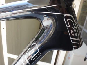
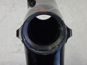
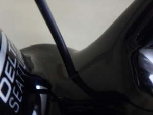
On both sides of the head tube and
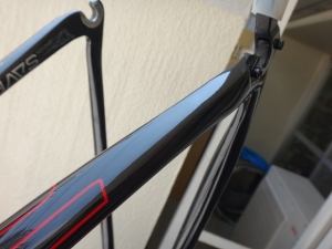
on the underside of the right chainstay, I just need to install cable bosses—
a simple job, or so I thought. At first.
I got three cable bosses from my mentor, who is also a frame builder.
I was never formally an apprentice to him, but he's my hero as a mechanic.
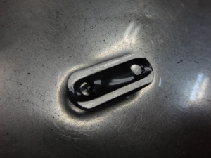
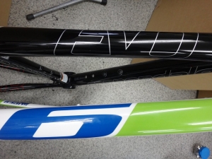
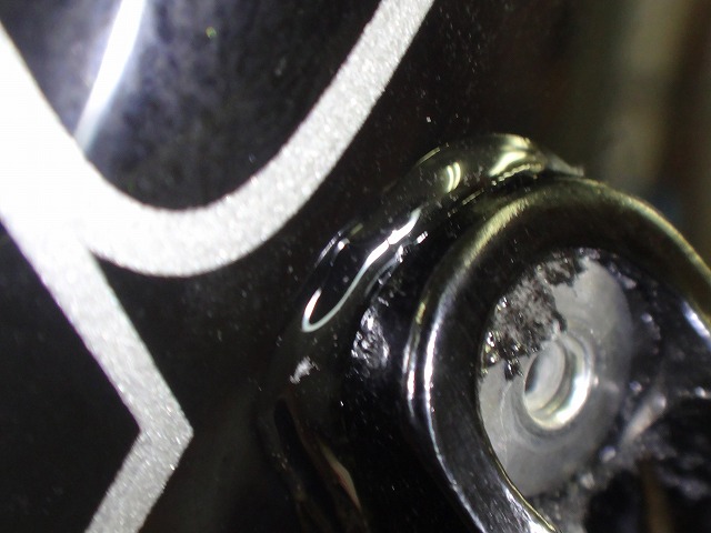
The underside was shaped to fit a round tube, so I filed it down flat.
In the photo, it's soaked in shallow water.
The black area still has some roundness,
but I'm stopping here because filing it completely would make the section where I rivet the nut too thin.
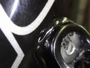
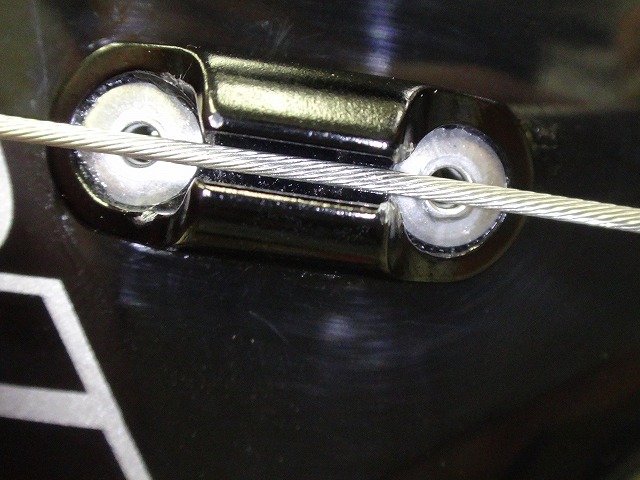
The adhesive I'm using as reinforcement (though it's far more critical to the holding strength than just "supplementary")
comes in two curing times: 5 minutes and 30 minutes.
Following my mentor's advice to avoid the 5-minute type proved to be the right call.
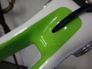
The excess adhesive showing in the photo gets wiped off later.
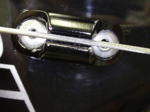
Getting the cable routing from the wire lead attached under the BB (bottom bracket)
to pass exactly through the slot is surprisingly difficult.
right
left
bottom

front
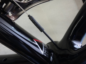
The cable boss on the down tube became necessary after dual-control levers arrived on the market.
Originally, it was a mounting point for bar-end shifter (W-lever) cable.
Since current race frames don't need to accommodate bar-end shifters,
manufacturers place simple cable bosses wherever they feel like,
but Giant was probably the first major manufacturer to put a cable boss on the side of the head tube with their TCR.
The downside of putting a cable boss on the head tube side is that
when you turn the handlebar, the shift outer cable gets pressed against the boss much harder
than it would if the boss were on the down tube,
so the cable housing covering gets damaged faster inside the outer cap.
Also, with a low handlebar position,
the cable routing becomes tight.
On the other hand, the advantage is that
if the boss is on the down tube,
the shift outer cable rubs against the frame near the head tube,
causing scuff marks on the frame
and wearing out the cable housing covering,
but with the head tube side boss, those problems don't occur.
Personally, I think the shift outer cable should be on the down tube
for better shifting performance and cable longevity,
with fewer problems overall—that's my preference.
But apparently many manufacturers these days think
the head tube side looks better,
and that's become the standard trend.
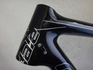
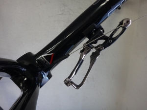
Also, the method used by Trek and Cannondale, among others, where the rear brake cable
runs from the front of the head tube (this frame does the same)
is clearly suboptimal from a cable routing perspective,
unless the frame size is exceptionally large.
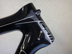
So why did I install the cable boss on the head tube side instead of the down tube this time?
Because this frame's down tube was abnormally thin.
Now I'm wondering if that's also why the rear brake outer cable boss
isn't positioned on the front of the top tube for the same reason.
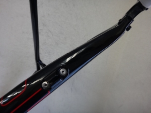
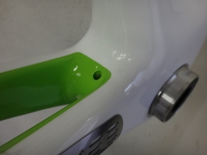
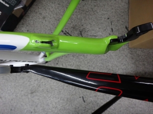
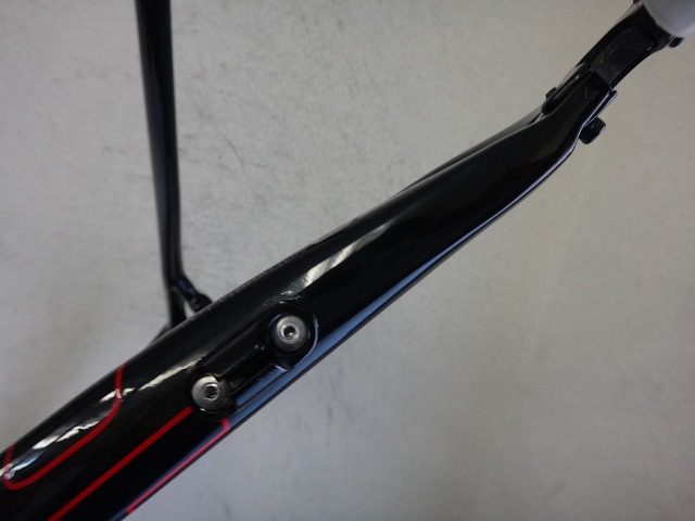
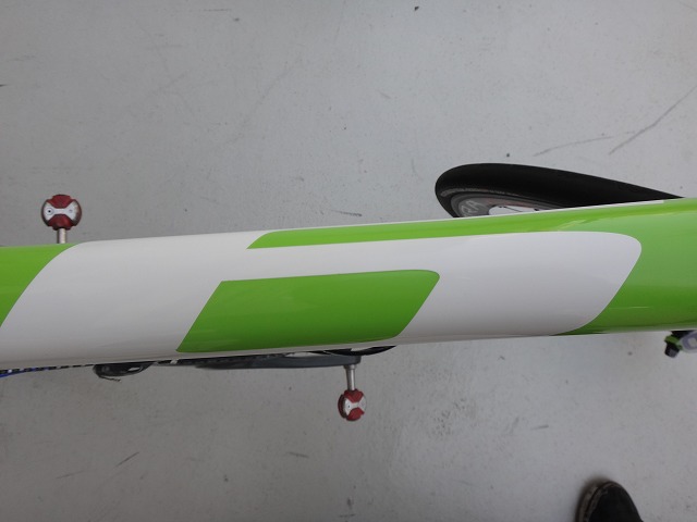
I also installed a cable boss on the right chainstay.
It might look offset to the outside, but
this position puts the shift cable routing exactly right.
I thought this would be all, but I forgot something important.
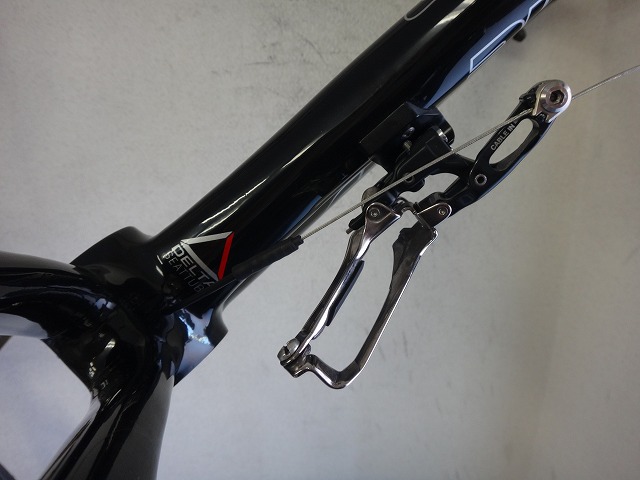
I need to create a path for the wire from the BB underside to the front derailleur.
This was incredibly difficult. The entrance under the BB is easy,
but creating an exit at exactly the right angle required a lot of thinking.
I'm using an FD-9000 (front derailleur) as a temporary guide,
but traditional front derailleurs without the cable anchor point
far from the parallelogram will also work.
Shift cables are 1.2mm diameter (in Shimano's case),
but I'm routing them through 3mm diameter liners to create the path,
so the cable will thread perfectly every time, even after pressing in the BB cups.

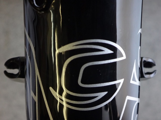
Regarding the Super Six EVO,
current models coming through Cannondale Japan
have "6" printed on the top tube instead of "EVO."
This is due to a trademark dispute with an automobile manufacturer that occurred in Japan.
So you can use this to tell whether a frame was imported from overseas or not,
but I'm not going to say which applies to this particular frame.
Separately, I received another Super Six EVO for BB cup pressing work.
Chronologically, this arrived before the cable boss job,
so seeing its positioning and routing was very helpful reference material.
BB top
BB underside
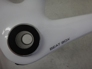
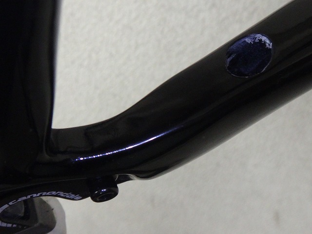
This hanger section, called a "Beat Box," has more volume compared to
the EVO I'm working on,
so I couldn't just copy the hole dimensions directly.

Head tube
Right chainstay
External battery (short seatpost bracket)

Front derailleur

Rear derailleur
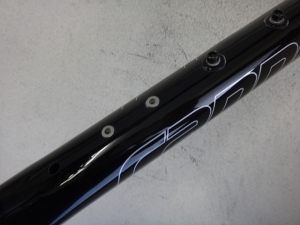
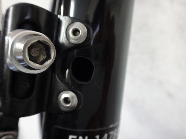
These are pre-existing holes, but
I wish they were drilled a bit more cleanly.

Not from a regular customer, but I received a Super Six EVO frame designed for Shimano Di2 (electronic drivetrain) from a former colleague in the bike industry.
He wants to build it up with mechanical drivetrain components and is asking me to install cable bosses (cable guides).
I told him, "If you're still in the industry, even as a former colleague, do it yourself,"
but he said that's impossible for a regular shop mechanic.
Hmm... that's harsh—it's like he's saying our shop isn't a normal bike shop.
Because there are political reasons related to his boss that I can't go against,
I reluctantly accepted the job.

On both sides of the head tube and

on the underside of the right chainstay, I just need to install cable bosses—
a simple job, or so I thought. At first.

I got three cable bosses from my mentor, who is also a frame builder.
I was never formally an apprentice to him, but he's my hero as a mechanic.
The underside was shaped to fit a round tube, so I filed it down flat.
In the photo, it's soaked in shallow water.
The black area still has some roundness,
but I'm stopping here because filing it completely would make the section where I rivet the nut too thin.
The adhesive I'm using as reinforcement (though it's far more critical to the holding strength than just "supplementary")
comes in two curing times: 5 minutes and 30 minutes.
Following my mentor's advice to avoid the 5-minute type proved to be the right call.
The excess adhesive showing in the photo gets wiped off later.
Getting the cable routing from the wire lead attached under the BB (bottom bracket)
to pass exactly through the slot is surprisingly difficult.

right

left

bottom
front
The cable boss on the down tube became necessary after dual-control levers arrived on the market.
Originally, it was a mounting point for bar-end shifter (W-lever) cable.
Since current race frames don't need to accommodate bar-end shifters,
manufacturers place simple cable bosses wherever they feel like,
but Giant was probably the first major manufacturer to put a cable boss on the side of the head tube with their TCR.
The downside of putting a cable boss on the head tube side is that
when you turn the handlebar, the shift outer cable gets pressed against the boss much harder
than it would if the boss were on the down tube,
so the cable housing covering gets damaged faster inside the outer cap.
Also, with a low handlebar position,
the cable routing becomes tight.
On the other hand, the advantage is that
if the boss is on the down tube,
the shift outer cable rubs against the frame near the head tube,
causing scuff marks on the frame
and wearing out the cable housing covering,
but with the head tube side boss, those problems don't occur.
Personally, I think the shift outer cable should be on the down tube
for better shifting performance and cable longevity,
with fewer problems overall—that's my preference.
But apparently many manufacturers these days think
the head tube side looks better,
and that's become the standard trend.
Also, the method used by Trek and Cannondale, among others, where the rear brake cable
runs from the front of the head tube (this frame does the same)
is clearly suboptimal from a cable routing perspective,
unless the frame size is exceptionally large.
So why did I install the cable boss on the head tube side instead of the down tube this time?
Because this frame's down tube was abnormally thin.
Now I'm wondering if that's also why the rear brake outer cable boss
isn't positioned on the front of the top tube for the same reason.
I also installed a cable boss on the right chainstay.
It might look offset to the outside, but
this position puts the shift cable routing exactly right.
I thought this would be all, but I forgot something important.
I need to create a path for the wire from the BB underside to the front derailleur.
This was incredibly difficult. The entrance under the BB is easy,
but creating an exit at exactly the right angle required a lot of thinking.
I'm using an FD-9000 (front derailleur) as a temporary guide,
but traditional front derailleurs without the cable anchor point
far from the parallelogram will also work.


Shift cables are 1.2mm diameter (in Shimano's case),
but I'm routing them through 3mm diameter liners to create the path,
so the cable will thread perfectly every time, even after pressing in the BB cups.
Regarding the Super Six EVO,
current models coming through Cannondale Japan
have "6" printed on the top tube instead of "EVO."
This is due to a trademark dispute with an automobile manufacturer that occurred in Japan.
So you can use this to tell whether a frame was imported from overseas or not,
but I'm not going to say which applies to this particular frame.

Separately, I received another Super Six EVO for BB cup pressing work.
Chronologically, this arrived before the cable boss job,
so seeing its positioning and routing was very helpful reference material.

BB top

BB underside

This hanger section, called a "Beat Box," has more volume compared to
the EVO I'm working on,
so I couldn't just copy the hole dimensions directly.
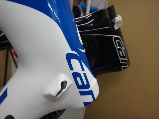
Head tube

Right chainstay

External battery (short seatpost bracket)
Front derailleur
Rear derailleur
These are pre-existing holes, but
I wish they were drilled a bit more cleanly.