Up until now, this blog has used the term "phase" without really defining it.
I should have written this much earlier, but it kept getting delayed, and here we are.
In this blog, "phase" refers to the angular positional relationship between
the spoke holes on the hub flanges and the nipple holes on the rim.
Whether the phase aligns perfectly is an extremely important issue.
You might think, "Does a wheel with misaligned phase even exist?"
But depending on how you pair hubs and rims, or how you build them,
it definitely can happen. I'll explain various cases.

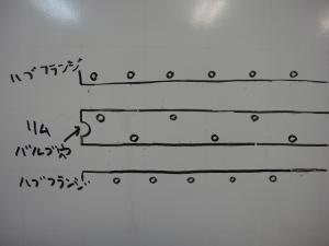
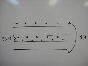
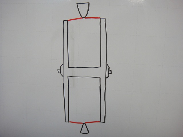
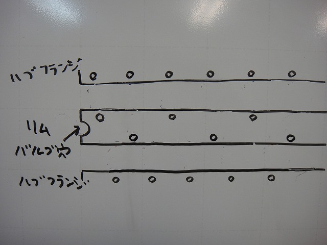
First, let me set up a mental model.
Imagine a wheel where the hub flange diameter equals the rim inner diameter.
Cut that wheel perpendicular to the direction of travel at the valve hole position,
and flatten it out.
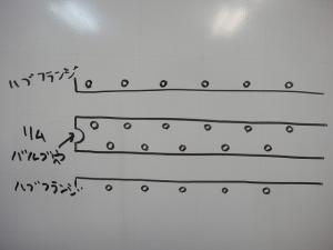
↑That's what you get. This is the basic model for thinking about phase.
First, I want to address something I'm occasionally asked about:
the phase misalignment when building a 36H hub with an 18H rim.
This applies not only to 36H hub / 18H rim,
but also whenever the rim hole count is half the hub hole count.
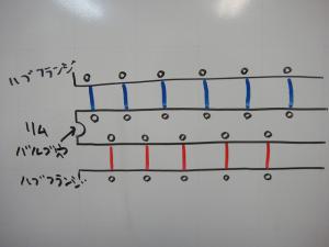
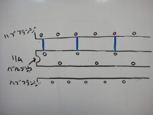
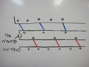
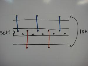
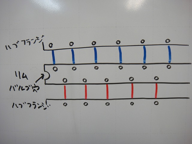
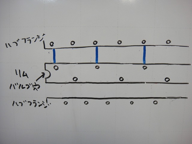
First, let me build a 36H hub with a 36H rim using radial lacing.
I've drawn the spokes on the near side (from my perspective) in red,
and the spokes on the far side in blue.
In radial lacing, the spoke lines run perpendicular to the direction of travel.
No phase misalignment occurs.
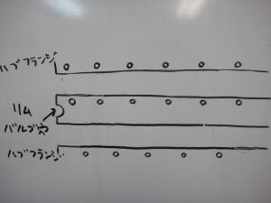
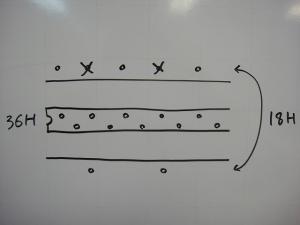
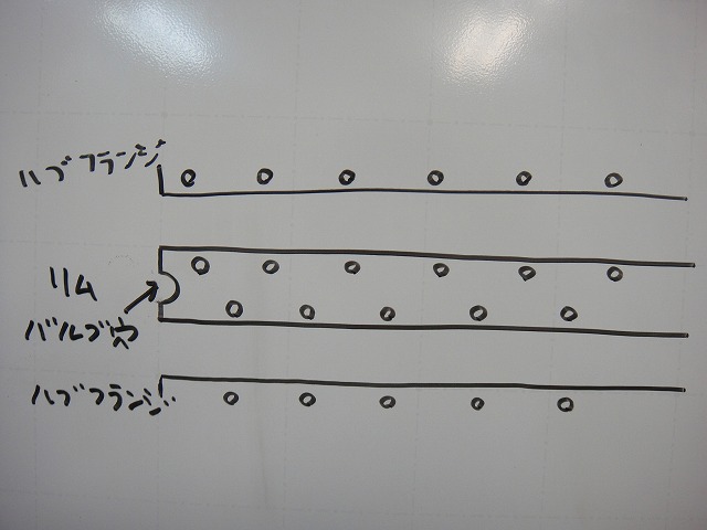
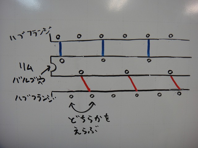
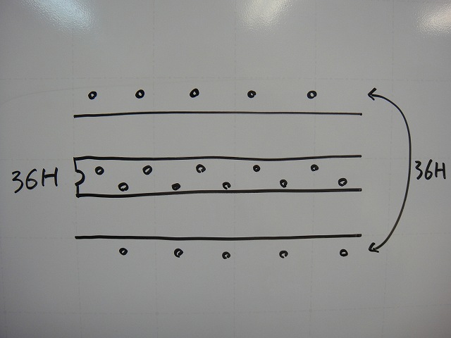
Now suppose the hub stays the same, but the rim's hole count is cut in half.
I've simply removed half of the rim holes for now.
I also need to correct the rim hole distribution to match the reduced hole count.
This is what it looks like.
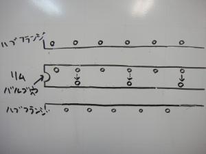
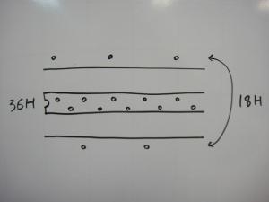
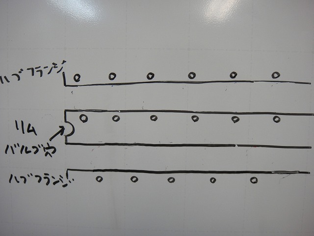
Let me try radial lacing just the far flange.
Looking at this alone, there's no phase misalignment.
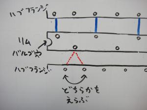
But on the other flange, at the position where the phase should align straight,
there's no corresponding spoke hole in the rim.
I have no choice but to place the spoke at a misaligned phase.
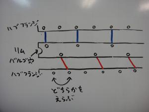
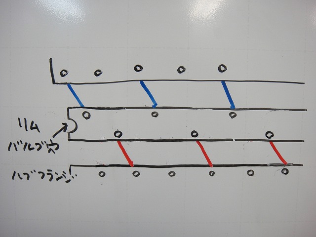
This is what it looks like when I run a spoke through.
Suppose I actually build it this way. Of course, the left and right spokes are the same length.
When I tension the spokes to center the rim . . .
. . . it stabilizes in this state.
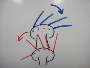
↑With an actual 18H rim and 36H hub, it's not quite this dramatic,
but the spokes (though it's misleading to call it "radial" lacing)
subtly twist—toward the porcupine direction on the near side
and toward the anti-porcupine direction on the far side. Feels odd, doesn't it?
You could say it's like JIS-spec inpoke only, with the outpoke missing.
In reality the twist is subtle, so you can ride it, but it doesn't feel right.

If I build this as tangent lacing, a real problem emerges.
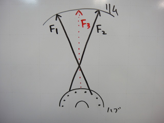
In normal tangent lacing with aligned phase, call the inpoke F1
and the outpoke F2. The resultant of their tension directions is F3 in the diagram above.
F3 is also the path the spoke takes in radial lacing.

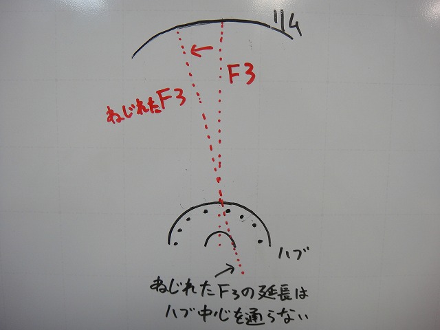
When F3 is twisted, that's the misaligned phase state.
If I extend the twisted F3 toward the hub, it won't pass through the hub axle.
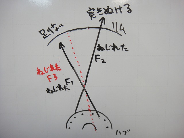
When I add F1 and F2 corresponding to this twisted F3:
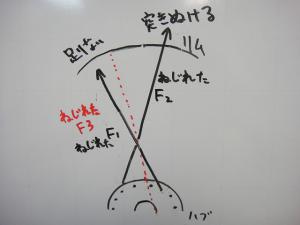
↑I get this. When F1 and F2 spokes are the same length,
the F1 spoke becomes too short to build,
and the F2 spoke becomes too long to build.
You'd need two different spoke lengths on one flange.
For a rear wheel, that means four different lengths for one wheel.
The 18H rim case has 9H per side (odd number), so tangent lacing isn't possible,
but with a 32H hub and 16H rim, this situation could arise.
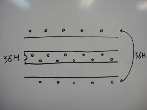
Next, consider building an 18H hub with a 36H rim.
Starting with the basic model:
I've removed all the holes from one flange.
In a normal hub, the flange holes are spaced evenly
in a left-right-left-right pattern,
so I shift every other spoke hole to the opposite flange.
This is the diagram for building with "a rim with twice the hub's hole count."
Let me try radial lacing right away.
↑No phase misalignment occurs, but only one side of the rim's hole pattern is being used.
If the rim has no hole offset, there's no problem.
But when building with "a rim with twice the hub's hole count,"
the realistic options are:
12H hub / 24H rim
16H hub / 32H rim
18H hub / 36H rim
A 14H hub / 28H rim would be essentially impossible in hand-building.
A 12H hub exists (like 7700 Dura-Ace),
but in practice it really comes down to two combinations:
"16H hub / 32H rim" and "18H hub / 36H rim."
Most 32H and 36H rims have spoke hole offset,
so building with "a rim with twice the hub's hole count" avoids phase misalignment,
but offset hole distribution does occur, so it still can't be called a proper wheel.
I should have written this much earlier, but it kept getting delayed, and here we are.
In this blog, "phase" refers to the angular positional relationship between
the spoke holes on the hub flanges and the nipple holes on the rim.
Whether the phase aligns perfectly is an extremely important issue.
You might think, "Does a wheel with misaligned phase even exist?"
But depending on how you pair hubs and rims, or how you build them,
it definitely can happen. I'll explain various cases.
First, let me set up a mental model.
Imagine a wheel where the hub flange diameter equals the rim inner diameter.
Cut that wheel perpendicular to the direction of travel at the valve hole position,
and flatten it out.
↑That's what you get. This is the basic model for thinking about phase.
First, I want to address something I'm occasionally asked about:
the phase misalignment when building a 36H hub with an 18H rim.
This applies not only to 36H hub / 18H rim,
but also whenever the rim hole count is half the hub hole count.
First, let me build a 36H hub with a 36H rim using radial lacing.
I've drawn the spokes on the near side (from my perspective) in red,
and the spokes on the far side in blue.
In radial lacing, the spoke lines run perpendicular to the direction of travel.
No phase misalignment occurs.
Now suppose the hub stays the same, but the rim's hole count is cut in half.
I've simply removed half of the rim holes for now.

I also need to correct the rim hole distribution to match the reduced hole count.
This is what it looks like.
Let me try radial lacing just the far flange.
Looking at this alone, there's no phase misalignment.

But on the other flange, at the position where the phase should align straight,
there's no corresponding spoke hole in the rim.
I have no choice but to place the spoke at a misaligned phase.
This is what it looks like when I run a spoke through.
Suppose I actually build it this way. Of course, the left and right spokes are the same length.
When I tension the spokes to center the rim . . .
. . . it stabilizes in this state.

↑With an actual 18H rim and 36H hub, it's not quite this dramatic,
but the spokes (though it's misleading to call it "radial" lacing)
subtly twist—toward the porcupine direction on the near side
and toward the anti-porcupine direction on the far side. Feels odd, doesn't it?
You could say it's like JIS-spec inpoke only, with the outpoke missing.
In reality the twist is subtle, so you can ride it, but it doesn't feel right.
If I build this as tangent lacing, a real problem emerges.
In normal tangent lacing with aligned phase, call the inpoke F1
and the outpoke F2. The resultant of their tension directions is F3 in the diagram above.
F3 is also the path the spoke takes in radial lacing.
When F3 is twisted, that's the misaligned phase state.
If I extend the twisted F3 toward the hub, it won't pass through the hub axle.
When I add F1 and F2 corresponding to this twisted F3:
↑I get this. When F1 and F2 spokes are the same length,
the F1 spoke becomes too short to build,
and the F2 spoke becomes too long to build.
You'd need two different spoke lengths on one flange.
For a rear wheel, that means four different lengths for one wheel.
The 18H rim case has 9H per side (odd number), so tangent lacing isn't possible,
but with a 32H hub and 16H rim, this situation could arise.
Next, consider building an 18H hub with a 36H rim.
Starting with the basic model:
I've removed all the holes from one flange.
In a normal hub, the flange holes are spaced evenly
in a left-right-left-right pattern,
so I shift every other spoke hole to the opposite flange.
This is the diagram for building with "a rim with twice the hub's hole count."
Let me try radial lacing right away.
↑No phase misalignment occurs, but only one side of the rim's hole pattern is being used.
If the rim has no hole offset, there's no problem.
But when building with "a rim with twice the hub's hole count,"
the realistic options are:
12H hub / 24H rim
16H hub / 32H rim
18H hub / 36H rim
A 14H hub / 28H rim would be essentially impossible in hand-building.
A 12H hub exists (like 7700 Dura-Ace),
but in practice it really comes down to two combinations:
"16H hub / 32H rim" and "18H hub / 36H rim."
Most 32H and 36H rims have spoke hole offset,
so building with "a rim with twice the hub's hole count" avoids phase misalignment,
but offset hole distribution does occur, so it still can't be called a proper wheel.