Another wheel day (and so on).
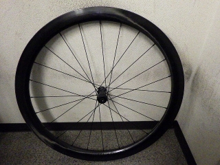
A customer brought in an ITLAB45 wheel.
Today I'm only working on the front wheel.
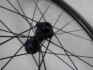
DT180 straight spoke hub 24H
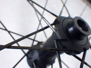
Custom titanium spokes by Pilar, laced with forced left-right 2-cross,
with all the final crossings on both sides of the front and rear wheels woven in.
The reason I took this wheel in was
that the nipples kept loosening.
Apparently the customer had it sent to ITLAB once and fixed,
but then it loosened again afterward.
The wheel came with an instruction manual written in some laughably nonsensical way,
but before I read that, the customer had already told me
that the original state of the wheel had soft tension,
and when it came back, it was strung super tight.
I don't fundamentally deny building a wheel with lower spoke tension
if there are reasons I can understand—weighing factors big and small—
that this is the best approach,
but building a wheel with lower spoke tension that doesn't loosen easily
is genuinely difficult.
If the builder of this wheel had some firm policy or philosophy
about intentionally building with lower tension,
I wouldn't criticize that itself,
but the fact that the customer could feel such a clear difference
in tension before and after sending the wheel, or even just by handling it,
means there's no consistency in spoke tension management.
If you're going to tension it back up and return it, then tension it properly from the start—
that's what I thought before reading the manual.
Oh, I did tell the customer "maybe just send it back to ITLAB",
but they were concerned the same problem would happen again,
so they decided to have us look at it.
In the end, I was able to identify what's likely causing the loosening.
So I read the manual,
and it says not to tension the spokes above 110 kgf.
The reference spoke tension is 100–105 kgf for both the brake side of the front wheel and the drive side of the rear wheel.
The phrasing "reference spoke tension" rather than specified, recommended, or limit tension,
and the phrasing "brake side" and "drive side" are exactly as written in the original manual, just so you know.
No, this is wrong.
The customer themselves could clearly feel the difference in tension before and after sending it,
but was it 100 kgf before and 105 kgf when it came back?
There's no way a 5 kgf difference would produce such a clear distinction—that's one thing.
The other is that no matter how precise the rim and how consistent the spokes,
within the range of actual materials that exist,
it's impossible to keep the spoke tension variation on one side of a wheel within 5 kgf.
For example, suppose you build a 24H wheel with a high-tension lower limit of 105 kgf
(of course, chasing runout and getting the center true is a given).
Then several of the 12 spokes on one side will exceed 110 kgf.
So if you build without ever exceeding 110 kgf,
you can only build with the upper limit at 105 kgf.
Then several of the 12 spokes on one side will fall below 100 kgf.
This itself is unavoidable.
If the high-tension side of the returned wheel doesn't exceed 110 kgf on a single spoke,
then the original state absolutely could not have been built at 100–105 kgf.
Also, the manual stated that you can measure this wheel's spoke tension with a DT tension meter,
but not with a Park Tool TM-1 or Hozan meter.
This is also wrong.
For this job, I'm completely disassembling the wheel and rebuilding it
to the same tension as when received, but in a way that won't loosen,
using the maximum H1ST value among the 12 high-tension spokes,
and even a Hozan tension meter can measure the wheel if I follow that after rebuilding.
Well, since it is specified,
I did use the DT tension meter,
but with D1ST and H1ST, for a given second ST (spoke tension in the general sense),
the Hozan meter showed no readings that deviated from the parabolic curve of first ST and second ST. Obviously.
Actually, from this job I made a conversion table from D1ST → second ST → H1ST,
so now with the same spokes I can also build wheels using the Hozan tension meter in the future.
Regarding the Park Tool TM-1, there are issues with large individual variation
and how easier the needle rises with adjustments to reduce friction in moving parts (including lubrication),
but as long as you're careful to use a specific unit in as consistent a condition as possible,
it's practically fine.
Since DT and Hozan tension meters are extremely expensive,
for hobby-level wheel building they're probably out of reach, so the TM-1 is quite valuable.
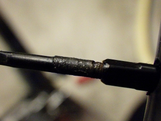
I loosened the nipples.
These nipples that you turn on the outer side—
the manual says absolutely don't grab the inner side.
I agree with that. I wouldn't anyway.
These nipples have unusually deep thread pockets,
and when you push a spoke into the nipple (without turning),
the spoke threads hide almost completely.
A thread-locking compound that dries rock-solid was used,
but this only prevents initial loosening and has almost no effect
on increasing friction on the threaded portion itself.
Actually, once the contact pressure between nipple and rim dropped away,
it turned extremely easily.
There's another reason for this (explained below).
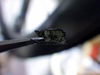
↑This fellow
Since the thread pockets are deep, the residue from the rock-solid compound is long too.
I forgot to write this, but the pre-work state had
about a sheet-of-paper's worth of center offset.
Depending on the centering gauge it would be spot-on,
so let's say the center was true.
Pre-work, I recorded all D1ST and H1ST values on the high-tension side.
I'm paying attention to the fact that spoke tension barely changed
between before and after work.
Also, there was tape marking where loosening had occurred, on the rear wheel spokes,
but knowing that, I worked on the front wheel first.
Since I know the H1ST of the front wheel high-tension side,
even if the rear wheel hub, rim, and spokes come to me separately,
I can now build the wheel at reference tension.
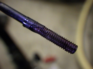
The most dangerous thing about this wheel is this:
Because they're titanium spokes,
anti-seize grease was applied generously
to the threads and the wheel was built like that.
Of course that's going to loosen.
This is the loosening cause I mentioned at the start,
and the reason the nipple turns so easily after the rock-solid thread-locking compound releases
as I described before.
Maybe the builder of this wheel will claim there's no causal relationship
between applying grease to the threads and nipple loosening,
but whether they completely disassembled or just re-tensioned without disassembling,
given the solid negative track record of a wheel with nipple loosening being worked on again
and loosening again afterward,
such a claim has no credibility.
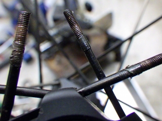
If rock-solid thread-locking compound is on the spokes,
you can't pull them out of the hub flange.
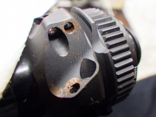
Anti-seize grease got on the hub flange area,
but I cleaned that up later.
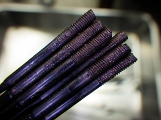
↑12 spokes from one side

I tilted a stainless pan
and sprayed parts cleaner on one edge of a corner.
Particles in the grease created convection swirls.
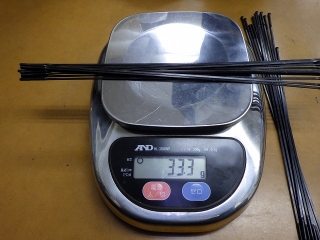
I'd call it a lazy design choice, but the left and right spoke lengths were identical.
I did separate them into original right and original left, though.
Since custom titanium spokes are expensive (about 6 times the cost of CX-RAY),
maybe they wanted to reduce the spare spoke inventory types.
Feel free to make up excuses later like "a disc brake front wheel with this much dish can handle the same length!"
It won't bother me—it just tells me
that's the level of understanding about spoke length that this builder has.
The 12 spokes from the original right side weighed 33.3g, and
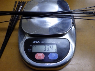
the 12 from the original left side were 33.4g.

The total for 24 spokes was 66.7g when added together.
Since the spoke length was 275mm,
the specific gravity is 66.7 (g) ÷ 275 (mm) ÷ 24 (spokes)
= 0.010106060...,
and dividing this by the standard reference value of 0.0257 for 100%
gives 0.039323219...,
so about 39.3%.
Straight spokes lack the kinked section after the neck bend that bent-neck spokes have—
it's not included in spoke length but is in weight—
so spoke specific gravity tends to come out slightly lower.
So for rough calculation, treating it as 40% is fine.
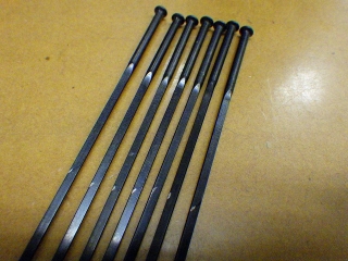
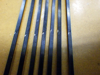
On some of the spokes from the original right side (anti-rotor side, low-tension side),
there were wear marks from rubbing at the final crossing.

I'll also clean the nipples.
The image above is not from soaking nipples in the parts cleaner used on spokes—
it's fresh parts cleaner sprayed after washing the pan.
So all the dirt that came out is from the nipples alone.
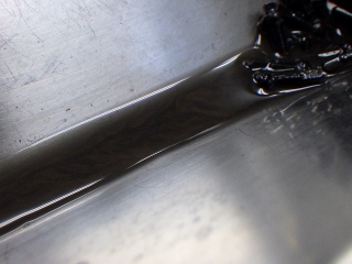
↑Tilting the pan and spraying on one edge looks like this
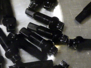
Parts cleaner is preliminary cleaning;
I then did ultrasonic cleaning.
The nipples in the image above are in water.
Right after switching on, black haze-like dirt was coming out from the nipple holes,
but I couldn't get a photo of that.
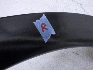
This rim doesn't look like an offset rim.
Even if it wasn't offset, there was once
a sticker saying "orient this side toward the rotor bracket on disc-brake front wheels,
or toward the freewheel body on rear wheels,"
and that might have fallen off and been lost,
so the original left-right orientation of the rim must not change with this rebuild.
So before disassembling, I marked the rim with tape saying "original right side is this side."
That's fine, but this rim has another problem.
This rim is a reverse-hole-offset rim.
I call a rim with standard hole spacing (what most rims in the world have, referenced to the valve hole)
a normal-hole rim,
and a rim with hole spacing mirrored opposite a reverse-hole rim.
For some reason, most Campagnolo and Fulcrum radial-laced front wheels
are reverse-hole rims.
Looking at what we have in the shop right now,
the Bora WTO rim-brake version front wheel is also reverse-hole.
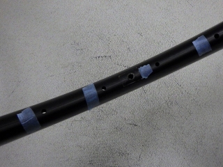
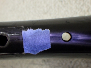
I placed tape next to four rim holes—two on each side, left and right—from the valve hole.
From here, I'll examine the hole spacing starting from the left in the image above.
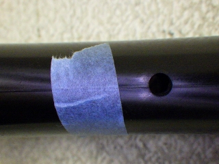
Due to rim molding perhaps, there's a line like a seam at the center,
but the rim hole in the image above is clearly
offset toward the upper side of that line.

I drew arrows showing the hole offset direction.
In the previous image, the rim hole interior was pitch black because I was pressing the rim against the wall,
but from here on I'm keeping it slightly away.
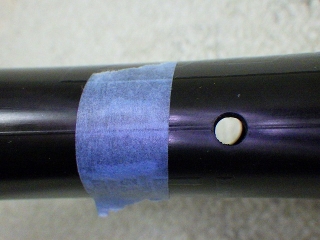
Next one.
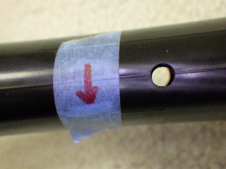
Clearly offset downward in the image.
Crossing over the valve hole, then the next one

Also clearly offset upward.

Finally the fourth one.
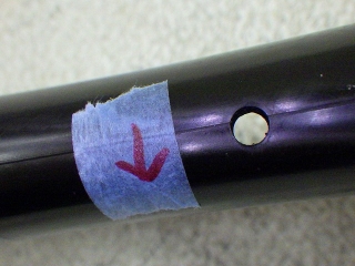
Also downward.
The apparent amount of offset relative to the centerline
isn't perfectly identical (rim precision issue),
but there wasn't any hole that looked so dead-center
that it was hard to judge.

So this rim is definitely reverse-hole offset.
And in the original state it was built as if it were normal-hole.
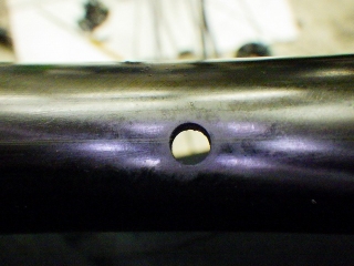
Separate from the valve hole area,
without the preconception that "holes alternate left-right,"
I'll mark each one individually on whichever side
clearly appears to have the offset.
For the hole in the image above,
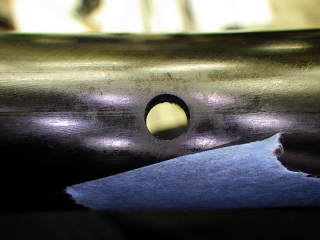
it's like this.
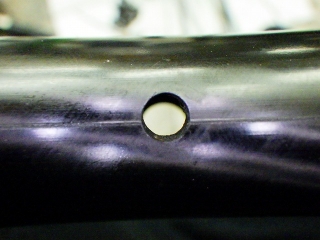
For this hole,
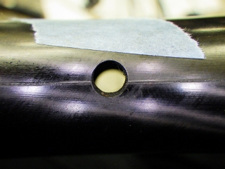
it's like this.
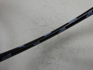
Then again, the tape ends up alternating left-right on the holes, and
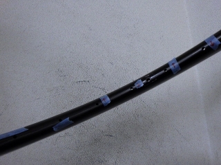
it matches up consistently with
the hole offset notes around the valve hole from before.
So what's the problem with reverse-hole rims? It's that
the DT forced left-right tangent-lace straight-spoke hub design
is designed for normal-hole rims.
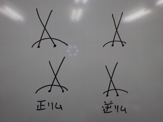
When you look at a normal-hole-offset wheel from the side,
of the left-right pair of spokes at the final crossing (4 spokes total),
the final crossing toward you
proceeds in a clockwise direction.
Reverse-hole is the opposite.
With bent-neck spokes and a generic bent-neck hub,
you can create the left-right pair for reverse-hole final crossing
by changing the initial right-drop or left-drop when threading spokes through the hub flange,
but a straight-spoke hub designed for normal-hole
can't change this.

Here's the 180 hub viewed from the right side.
For work convenience I threaded all the spokes in the outpoke direction first from the left flange,

but ignore the five irrelevant ones.
This is the final crossing pair shape for normal-hole.
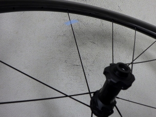
Following the rim hole spacing,
I decided to build with a normal-hole hub
and a reverse-hole rim.
The spoke with the tape mark in the image
comes out from the flange on the lower side of the image,
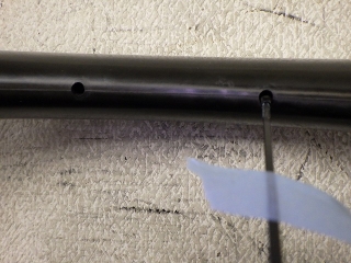
and it matches the hole spacing. Or rather, I made it match.
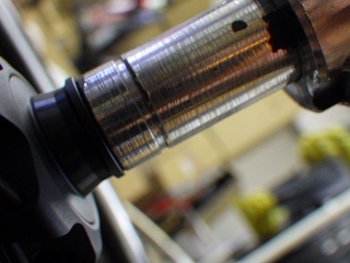
Center dead-on, with spoke tension essentially the same as before,
I rebuilt it.
This time I didn't even increase it slightly.
Using the thread-locking compound we normally use in the shop (not rock-solid),
I applied it to the spoke threads after degreasing.
Since this wheel was built by our shop,
future truing work and such are free.
Hopefully it won't loosen...
By the way, outside the scope of the original request,
I'm confident I could do a rebuild with steel spokes using this hub and rim
that would make the bike feel heavier when held
but actually quicker-feeling and better-performing overall.
I have a plan toprove this in a crude way,
but I can't do it right now.Hehehehe.

Built.
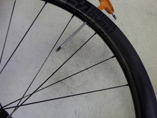
The valve hole phase ends up
within the left-right pair of the final crossing (4 spokes),
but this is unavoidable given the hub design.
I find getting the hole spacing wrong more annoying than this,
so that's what I did.
Also, even without anti-seize grease on the titanium spoke threads,
I felt no sense of seizing at all during wheel building.
To the builder or designer of this wheel:
If there's some rational reason that would convince me
about why the rim holes were reverse-offset,
please tell me.

A customer brought in an ITLAB45 wheel.
Today I'm only working on the front wheel.

DT180 straight spoke hub 24H

Custom titanium spokes by Pilar, laced with forced left-right 2-cross,
with all the final crossings on both sides of the front and rear wheels woven in.
The reason I took this wheel in was
that the nipples kept loosening.
Apparently the customer had it sent to ITLAB once and fixed,
but then it loosened again afterward.
The wheel came with an instruction manual written in some laughably nonsensical way,
but before I read that, the customer had already told me
that the original state of the wheel had soft tension,
and when it came back, it was strung super tight.
I don't fundamentally deny building a wheel with lower spoke tension
if there are reasons I can understand—weighing factors big and small—
that this is the best approach,
but building a wheel with lower spoke tension that doesn't loosen easily
is genuinely difficult.
If the builder of this wheel had some firm policy or philosophy
about intentionally building with lower tension,
I wouldn't criticize that itself,
but the fact that the customer could feel such a clear difference
in tension before and after sending the wheel, or even just by handling it,
means there's no consistency in spoke tension management.
If you're going to tension it back up and return it, then tension it properly from the start—
that's what I thought before reading the manual.
Oh, I did tell the customer "maybe just send it back to ITLAB",
but they were concerned the same problem would happen again,
so they decided to have us look at it.
In the end, I was able to identify what's likely causing the loosening.
So I read the manual,
and it says not to tension the spokes above 110 kgf.
The reference spoke tension is 100–105 kgf for both the brake side of the front wheel and the drive side of the rear wheel.
The phrasing "reference spoke tension" rather than specified, recommended, or limit tension,
and the phrasing "brake side" and "drive side" are exactly as written in the original manual, just so you know.
No, this is wrong.
The customer themselves could clearly feel the difference in tension before and after sending it,
but was it 100 kgf before and 105 kgf when it came back?
There's no way a 5 kgf difference would produce such a clear distinction—that's one thing.
The other is that no matter how precise the rim and how consistent the spokes,
within the range of actual materials that exist,
it's impossible to keep the spoke tension variation on one side of a wheel within 5 kgf.
For example, suppose you build a 24H wheel with a high-tension lower limit of 105 kgf
(of course, chasing runout and getting the center true is a given).
Then several of the 12 spokes on one side will exceed 110 kgf.
So if you build without ever exceeding 110 kgf,
you can only build with the upper limit at 105 kgf.
Then several of the 12 spokes on one side will fall below 100 kgf.
This itself is unavoidable.
If the high-tension side of the returned wheel doesn't exceed 110 kgf on a single spoke,
then the original state absolutely could not have been built at 100–105 kgf.
Also, the manual stated that you can measure this wheel's spoke tension with a DT tension meter,
but not with a Park Tool TM-1 or Hozan meter.
This is also wrong.
For this job, I'm completely disassembling the wheel and rebuilding it
to the same tension as when received, but in a way that won't loosen,
using the maximum H1ST value among the 12 high-tension spokes,
and even a Hozan tension meter can measure the wheel if I follow that after rebuilding.
Well, since it is specified,
I did use the DT tension meter,
but with D1ST and H1ST, for a given second ST (spoke tension in the general sense),
the Hozan meter showed no readings that deviated from the parabolic curve of first ST and second ST. Obviously.
Actually, from this job I made a conversion table from D1ST → second ST → H1ST,
so now with the same spokes I can also build wheels using the Hozan tension meter in the future.
Regarding the Park Tool TM-1, there are issues with large individual variation
and how easier the needle rises with adjustments to reduce friction in moving parts (including lubrication),
but as long as you're careful to use a specific unit in as consistent a condition as possible,
it's practically fine.
Since DT and Hozan tension meters are extremely expensive,
for hobby-level wheel building they're probably out of reach, so the TM-1 is quite valuable.

I loosened the nipples.
These nipples that you turn on the outer side—
the manual says absolutely don't grab the inner side.
I agree with that. I wouldn't anyway.
These nipples have unusually deep thread pockets,
and when you push a spoke into the nipple (without turning),
the spoke threads hide almost completely.
A thread-locking compound that dries rock-solid was used,
but this only prevents initial loosening and has almost no effect
on increasing friction on the threaded portion itself.
Actually, once the contact pressure between nipple and rim dropped away,
it turned extremely easily.
There's another reason for this (explained below).

↑This fellow
Since the thread pockets are deep, the residue from the rock-solid compound is long too.
I forgot to write this, but the pre-work state had
about a sheet-of-paper's worth of center offset.
Depending on the centering gauge it would be spot-on,
so let's say the center was true.
Pre-work, I recorded all D1ST and H1ST values on the high-tension side.
I'm paying attention to the fact that spoke tension barely changed
between before and after work.
Also, there was tape marking where loosening had occurred, on the rear wheel spokes,
but knowing that, I worked on the front wheel first.
Since I know the H1ST of the front wheel high-tension side,
even if the rear wheel hub, rim, and spokes come to me separately,
I can now build the wheel at reference tension.

The most dangerous thing about this wheel is this:
Because they're titanium spokes,
anti-seize grease was applied generously
to the threads and the wheel was built like that.
Of course that's going to loosen.
This is the loosening cause I mentioned at the start,
and the reason the nipple turns so easily after the rock-solid thread-locking compound releases
as I described before.
Maybe the builder of this wheel will claim there's no causal relationship
between applying grease to the threads and nipple loosening,
but whether they completely disassembled or just re-tensioned without disassembling,
given the solid negative track record of a wheel with nipple loosening being worked on again
and loosening again afterward,
such a claim has no credibility.

If rock-solid thread-locking compound is on the spokes,
you can't pull them out of the hub flange.

Anti-seize grease got on the hub flange area,
but I cleaned that up later.

↑12 spokes from one side

I tilted a stainless pan
and sprayed parts cleaner on one edge of a corner.
Particles in the grease created convection swirls.

I'd call it a lazy design choice, but the left and right spoke lengths were identical.
I did separate them into original right and original left, though.
Since custom titanium spokes are expensive (about 6 times the cost of CX-RAY),
maybe they wanted to reduce the spare spoke inventory types.
Feel free to make up excuses later like "a disc brake front wheel with this much dish can handle the same length!"
It won't bother me—it just tells me
that's the level of understanding about spoke length that this builder has.
The 12 spokes from the original right side weighed 33.3g, and

the 12 from the original left side were 33.4g.

The total for 24 spokes was 66.7g when added together.
Since the spoke length was 275mm,
the specific gravity is 66.7 (g) ÷ 275 (mm) ÷ 24 (spokes)
= 0.010106060...,
and dividing this by the standard reference value of 0.0257 for 100%
gives 0.039323219...,
so about 39.3%.
Straight spokes lack the kinked section after the neck bend that bent-neck spokes have—
it's not included in spoke length but is in weight—
so spoke specific gravity tends to come out slightly lower.
So for rough calculation, treating it as 40% is fine.


On some of the spokes from the original right side (anti-rotor side, low-tension side),
there were wear marks from rubbing at the final crossing.

I'll also clean the nipples.
The image above is not from soaking nipples in the parts cleaner used on spokes—
it's fresh parts cleaner sprayed after washing the pan.
So all the dirt that came out is from the nipples alone.

↑Tilting the pan and spraying on one edge looks like this

Parts cleaner is preliminary cleaning;
I then did ultrasonic cleaning.
The nipples in the image above are in water.
Right after switching on, black haze-like dirt was coming out from the nipple holes,
but I couldn't get a photo of that.

This rim doesn't look like an offset rim.
Even if it wasn't offset, there was once
a sticker saying "orient this side toward the rotor bracket on disc-brake front wheels,
or toward the freewheel body on rear wheels,"
and that might have fallen off and been lost,
so the original left-right orientation of the rim must not change with this rebuild.
So before disassembling, I marked the rim with tape saying "original right side is this side."
That's fine, but this rim has another problem.
This rim is a reverse-hole-offset rim.
I call a rim with standard hole spacing (what most rims in the world have, referenced to the valve hole)
a normal-hole rim,
and a rim with hole spacing mirrored opposite a reverse-hole rim.
For some reason, most Campagnolo and Fulcrum radial-laced front wheels
are reverse-hole rims.
Looking at what we have in the shop right now,
the Bora WTO rim-brake version front wheel is also reverse-hole.

I placed tape next to four rim holes—two on each side, left and right—from the valve hole.
From here, I'll examine the hole spacing starting from the left in the image above.

Due to rim molding perhaps, there's a line like a seam at the center,
but the rim hole in the image above is clearly
offset toward the upper side of that line.

I drew arrows showing the hole offset direction.
In the previous image, the rim hole interior was pitch black because I was pressing the rim against the wall,
but from here on I'm keeping it slightly away.

Next one.

Clearly offset downward in the image.

Crossing over the valve hole, then the next one

Also clearly offset upward.

Finally the fourth one.

Also downward.
The apparent amount of offset relative to the centerline
isn't perfectly identical (rim precision issue),
but there wasn't any hole that looked so dead-center
that it was hard to judge.

So this rim is definitely reverse-hole offset.
And in the original state it was built as if it were normal-hole.

Separate from the valve hole area,
without the preconception that "holes alternate left-right,"
I'll mark each one individually on whichever side
clearly appears to have the offset.
For the hole in the image above,

it's like this.

For this hole,

it's like this.

Then again, the tape ends up alternating left-right on the holes, and

it matches up consistently with
the hole offset notes around the valve hole from before.
So what's the problem with reverse-hole rims? It's that
the DT forced left-right tangent-lace straight-spoke hub design
is designed for normal-hole rims.

When you look at a normal-hole-offset wheel from the side,
of the left-right pair of spokes at the final crossing (4 spokes total),
the final crossing toward you
proceeds in a clockwise direction.
Reverse-hole is the opposite.
With bent-neck spokes and a generic bent-neck hub,
you can create the left-right pair for reverse-hole final crossing
by changing the initial right-drop or left-drop when threading spokes through the hub flange,
but a straight-spoke hub designed for normal-hole
can't change this.

Here's the 180 hub viewed from the right side.
For work convenience I threaded all the spokes in the outpoke direction first from the left flange,

but ignore the five irrelevant ones.
This is the final crossing pair shape for normal-hole.

Following the rim hole spacing,
I decided to build with a normal-hole hub
and a reverse-hole rim.
The spoke with the tape mark in the image
comes out from the flange on the lower side of the image,

and it matches the hole spacing. Or rather, I made it match.


Center dead-on, with spoke tension essentially the same as before,
I rebuilt it.
This time I didn't even increase it slightly.
Using the thread-locking compound we normally use in the shop (not rock-solid),
I applied it to the spoke threads after degreasing.
Since this wheel was built by our shop,
future truing work and such are free.
Hopefully it won't loosen...
By the way, outside the scope of the original request,
I'm confident I could do a rebuild with steel spokes using this hub and rim
that would make the bike feel heavier when held
but actually quicker-feeling and better-performing overall.
I have a plan to
but I can't do it right now.

Built.
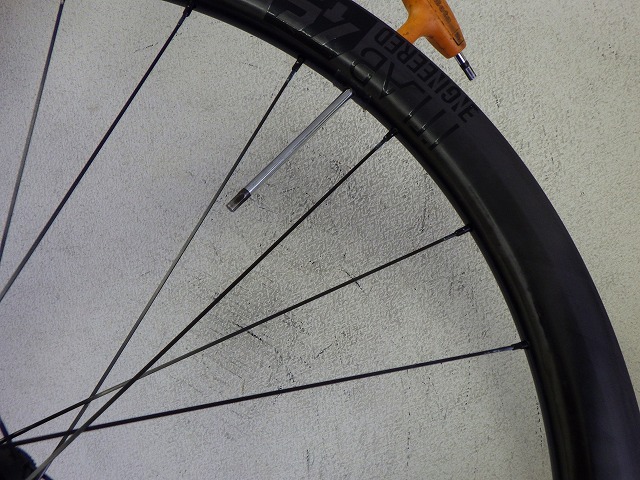
The valve hole phase ends up
within the left-right pair of the final crossing (4 spokes),
but this is unavoidable given the hub design.
I find getting the hole spacing wrong more annoying than this,
so that's what I did.
Also, even without anti-seize grease on the titanium spoke threads,
I felt no sense of seizing at all during wheel building.
To the builder or designer of this wheel:
If there's some rational reason that would convince me
about why the rim holes were reverse-offset,
please tell me.
Products Mentioned in This Article
- 🛒 DT180 straight spoke bicycle hub
- 🛒 Pillar titanium bladed spokes
- 🛒 DT Swiss spoke tension meter
- 🛒 Hozan spoke tension meter
* Amazon affiliate links — prices may vary
Original Japanese post: のむラボ日記 #6452