When I wrote about asymmetrical left-right lacing the other day,
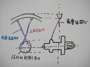
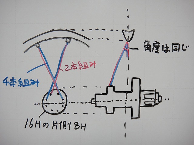
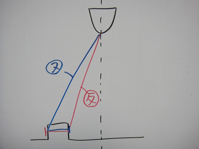
I drew a diagram like this, and it contains the notation "angle is the same."
This means "the angle between the wheel centerline and the spokes remains constant regardless of how many crosses in X-cross lacing,"
but I received a comment saying "I don't believe that."
To be blunt, I was wrong.
Thank you for pointing that out.
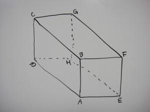
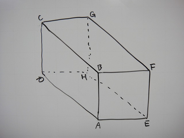
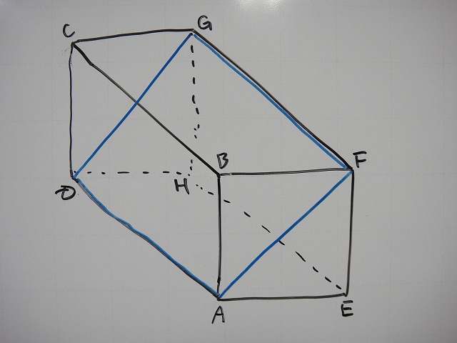
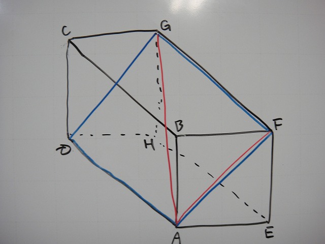
↑Let's consider a rectangular prism like this.

When I slice it diagonally in half, I add the plane AFGD formed by that slice.

I draw straight lines from A to F and from A to G.

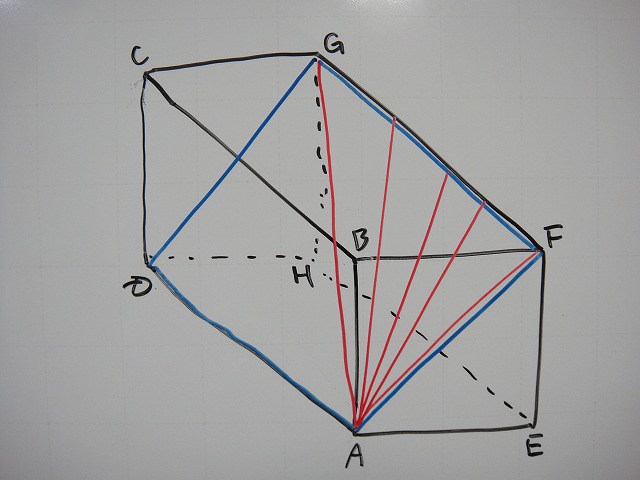
Furthermore, I draw several arbitrary straight lines from A toward the line segment FG.
Since all these red lines lie on plane AFGD,
when viewing this rectangular prism straight-on
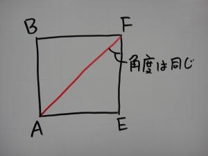
all the red lines become collinear. This is where I made my misconception.
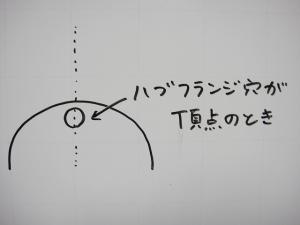
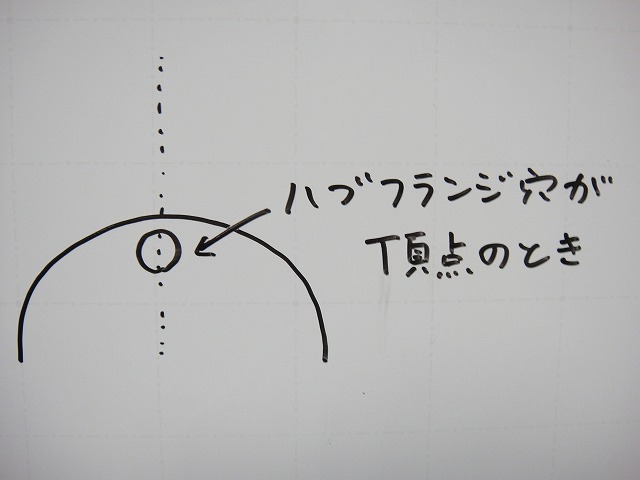
Let me reconsider using "the direction of extension of X-cross spokes exiting from a hub flange hole when that hole is positioned at the apex" as the reference.
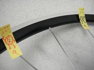
Below, I'll discuss the direction of the spoke colored red.
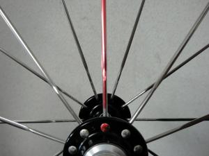
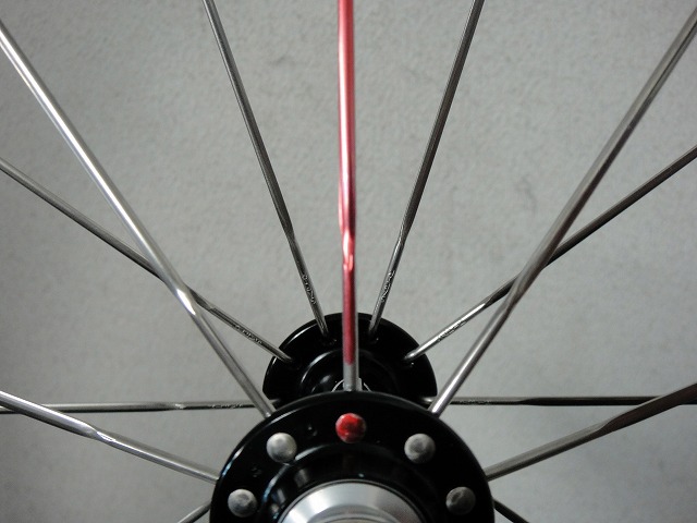
I've used outpoke lacing since it makes the spoke head easier to see.
For radial lacing, it looks like this.
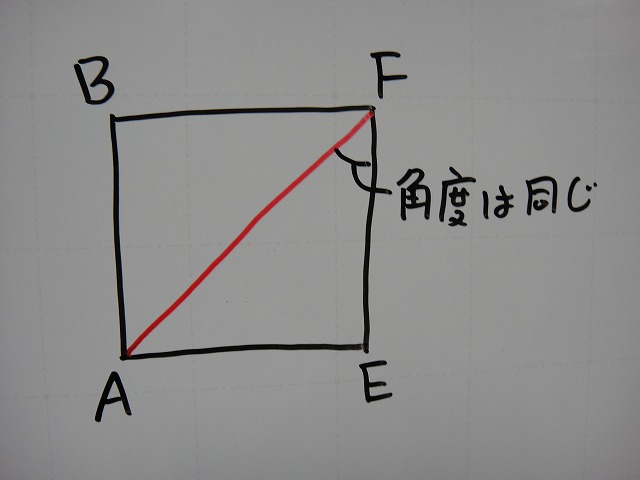
It's perpendicular to the horizontal plane (ground), so it's 90°.

For a certain 32H 4-cross lacing, it's about like this.
Even though it's called "4-cross," the angle isn't constant—
it varies with flange diameter, rim depth, and especially spoke count.
To give an extreme example, if you had around 1000H,
the angle would end up almost the same as radial lacing.

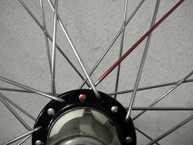
For a certain 32H 8-cross lacing, it's about like this.
32H 8-cross is maximum tangential lacing,
and the angle is roughly a bit less than horizontal.
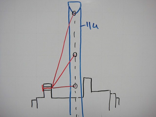
Plotting these looks something like this.
"The angles are not the same."
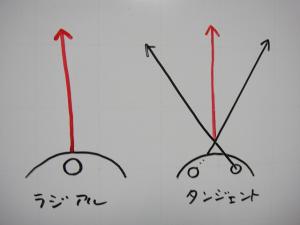
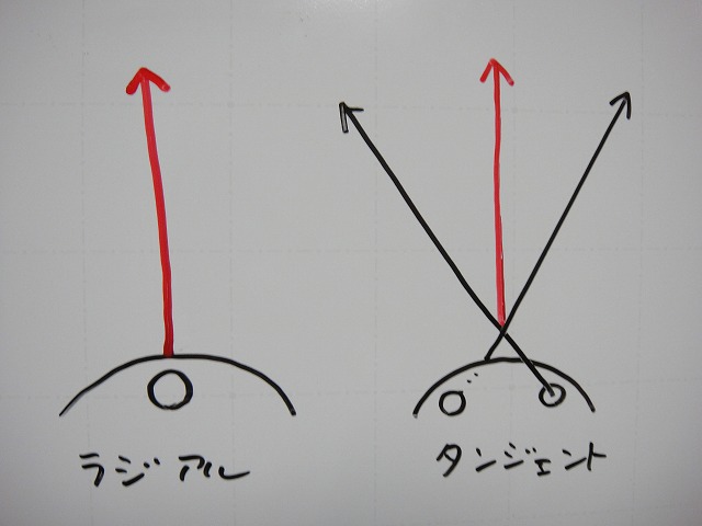
Next, I'll consider using "when the spoke tension direction is straight up" as the reference.
Regarding spoke tension direction: for radial lacing it's the spoke extension direction itself;
for tangential lacing I consider it the resultant direction of the two spokes in the final crossover.
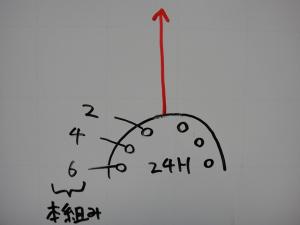
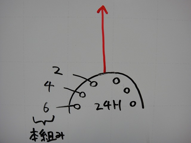
Assuming a 24H hub and not considering crossovers beyond the hub bisector,
tangential lacing can have 2-cross, 4-cross, or 6-cross patterns.
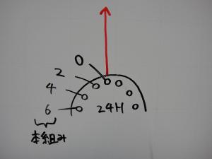
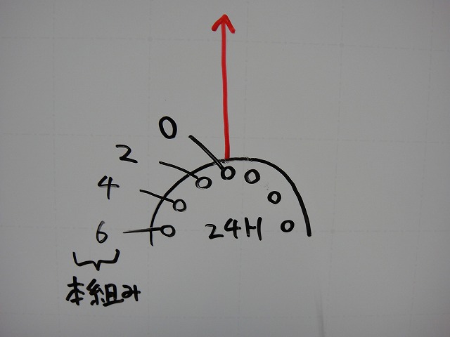
I've added 0-cross (radial lacing) to this.
Since I'm using spoke tension direction as the reference,
only the 0-cross differs in hub hole phase.
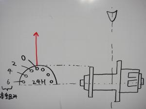
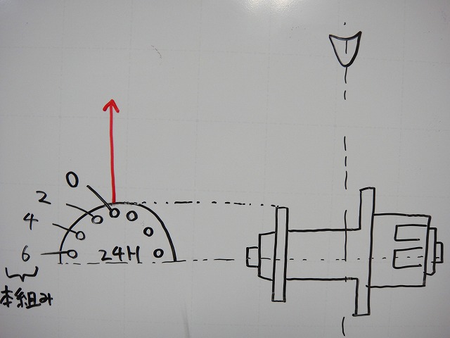
When I map this into a diagram like this . . .
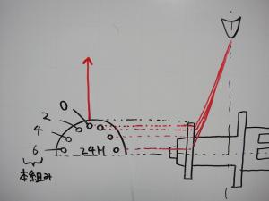
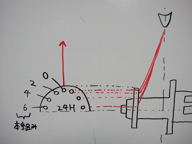
. . . it comes out like this.
"The angles are not the same."
In the comment, the author wrote something to the effect that "radial lacing has a blunt angle, while maximum tangential lacing has a sharp angle,"
and I think the second diagram I showed above would be better for expressing that concept than the first one.
The comment was very helpful.
Thank you.
My principle is generally not to modify or delete past posts except for typos and grammatical errors,
so I'm linking this correction post from the original article.
As a side note, the angle also changes between inpoke and outpoke lacing.
This is for radial lacing; for tangential lacing, typically both inpoke and outpoke are laced,
so which spoke is actually on the outside of the wheel depends on the position.
When the wheel is laid on its side and I call the outer side "up,"

at the hub flange, inpoke is up, but

at the spoke crossover (where they're woven), outpoke is up.
However, I suspect that at the nipple section, the up-and-down relationship converges.
The angles are the same, or nearly indifferent.
Also, the comment mentioned "spoke length has never been stated before,"
and that's because it touches on the Meshinotane Code.
It's not the spoke length itself I'd be touching on,
but because of "a certain thing" I'd be giving away if I wrote it out—something some people might notice.
Oops, close call.
I drew a diagram like this, and it contains the notation "angle is the same."
This means "the angle between the wheel centerline and the spokes remains constant regardless of how many crosses in X-cross lacing,"
but I received a comment saying "I don't believe that."
To be blunt, I was wrong.
Thank you for pointing that out.
↑Let's consider a rectangular prism like this.
When I slice it diagonally in half, I add the plane AFGD formed by that slice.
I draw straight lines from A to F and from A to G.
Furthermore, I draw several arbitrary straight lines from A toward the line segment FG.
Since all these red lines lie on plane AFGD,
when viewing this rectangular prism straight-on
all the red lines become collinear. This is where I made my misconception.
Let me reconsider using "the direction of extension of X-cross spokes exiting from a hub flange hole when that hole is positioned at the apex" as the reference.
Below, I'll discuss the direction of the spoke colored red.
I've used outpoke lacing since it makes the spoke head easier to see.
For radial lacing, it looks like this.
It's perpendicular to the horizontal plane (ground), so it's 90°.
For a certain 32H 4-cross lacing, it's about like this.
Even though it's called "4-cross," the angle isn't constant—
it varies with flange diameter, rim depth, and especially spoke count.
To give an extreme example, if you had around 1000H,
the angle would end up almost the same as radial lacing.

For a certain 32H 8-cross lacing, it's about like this.
32H 8-cross is maximum tangential lacing,
and the angle is roughly a bit less than horizontal.
Plotting these looks something like this.
"The angles are not the same."
Next, I'll consider using "when the spoke tension direction is straight up" as the reference.
Regarding spoke tension direction: for radial lacing it's the spoke extension direction itself;
for tangential lacing I consider it the resultant direction of the two spokes in the final crossover.
Assuming a 24H hub and not considering crossovers beyond the hub bisector,
tangential lacing can have 2-cross, 4-cross, or 6-cross patterns.
I've added 0-cross (radial lacing) to this.
Since I'm using spoke tension direction as the reference,
only the 0-cross differs in hub hole phase.
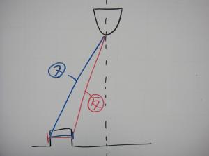
When I map this into a diagram like this . . .
. . . it comes out like this.
"The angles are not the same."
In the comment, the author wrote something to the effect that "radial lacing has a blunt angle, while maximum tangential lacing has a sharp angle,"
and I think the second diagram I showed above would be better for expressing that concept than the first one.
The comment was very helpful.
Thank you.
My principle is generally not to modify or delete past posts except for typos and grammatical errors,
so I'm linking this correction post from the original article.
As a side note, the angle also changes between inpoke and outpoke lacing.
This is for radial lacing; for tangential lacing, typically both inpoke and outpoke are laced,
so which spoke is actually on the outside of the wheel depends on the position.
When the wheel is laid on its side and I call the outer side "up,"

at the hub flange, inpoke is up, but
at the spoke crossover (where they're woven), outpoke is up.
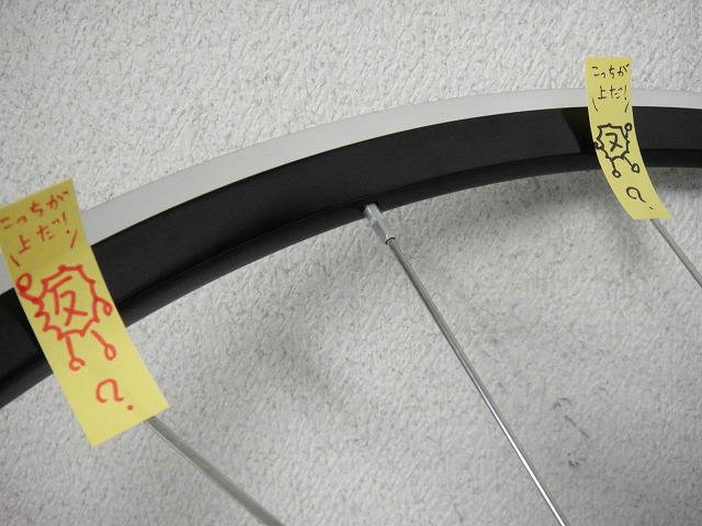
However, I suspect that at the nipple section, the up-and-down relationship converges.
The angles are the same, or nearly indifferent.
Also, the comment mentioned "spoke length has never been stated before,"
and that's because it touches on the Meshinotane Code.
It's not the spoke length itself I'd be touching on,
but because of "a certain thing" I'd be giving away if I wrote it out—something some people might notice.
Oops, close call.