Today was more wheel work (and then some)
It doesn't fall under the usual category, but
it actually took even more work time than that.

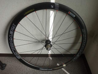
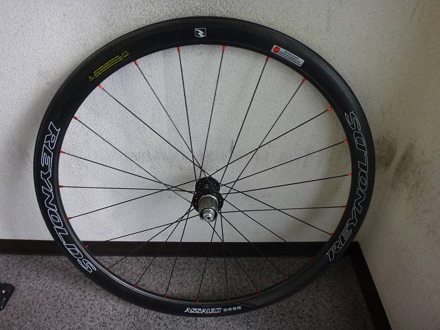
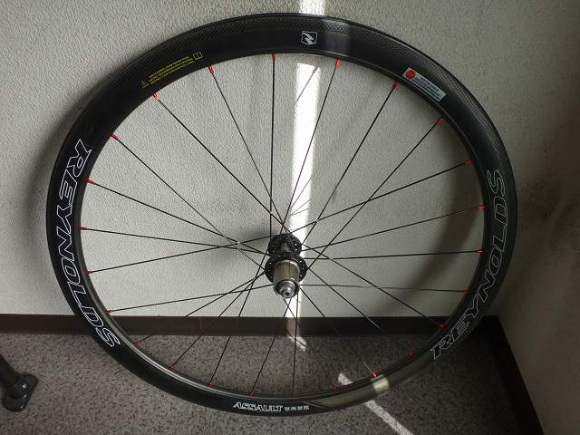
A customer brought in a Reynolds Assault rear wheel.
The person who brought it is the owner, but a friend had rebuilt it,
and they wanted me to do the spoke tensioning and solder the spokes.
Our shop gets customers from far away pretty often,
but this customer came directly by express bus from the Kanto region.
They're taking the bullet train back home.
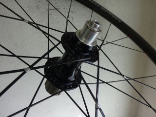
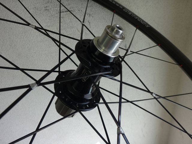
After the rebuild, the setup is:
Evolight hub 24-hole black Compe / Aerolight 46-spoke lacing.
The spoke weight distribution is almost the same as half-Compe
(Compe/CX-RAY), so it's basically the same spec.
As I've mentioned before,
when I only do spoke tensioning on a wheel I didn't build myself,
if the truing accuracy or tension is below my acceptable standard,
I do corrective adjustments, and if even that doesn't reach my standard,
I won't do the work.
I know that sounds pretty arrogant to say,
but this builder seems to be asking "How does this look? Check it out!"
so I'll be frank about it.
Almost no lateral runout, dead center,
and not a single stripped nipple — that was the condition.
There are pseudo-pro shops out there that touch stock Reynolds wheels
under the guise of inspection, then shift the center and strip nipples
(→here),
so for amateur work, this was excellent.
There was just a faint amount of radial runout that hadn't been completely corrected.
I had the customer check the amount of radial runout before and after the work.
But that was pretty minor stuff—
nothing you'd actually feel while riding.
As for spoke tension, there was still room to tighten.
You can't just keep tightening more and more, but it could still go tighter.
This is where it gets tricky, I think.
I showed the customer three stages of values on our Hozan tension meter
(H1ST — Hozan's First Spoke Tension reading).
For the actual work, first I loosened the non-drive side nipples exactly 3 full turns.
From there, I tightened the drive side
and ended up tightening it by about 2 turns total.
The first phase of that was 1 turn per spoke.
At the same time as tightening the drive side, I also made fine radial runout corrections.
Then I tightened the non-drive side nipples again by 3 full turns.
Since I'd tightened the drive side, the wheel center had shifted toward the drive side.
From that point, until the wheel center came back into true,
I could keep tightening the non-drive side one-directionally —
that's what I call the "tightening bonus."
The H1ST reading on the drive side before the work (A) when the center was dead-on,
and the H1ST reading on the drive side at the point of greatest center deviation
(from non-drive minus 3 turns to drive plus about 2 turns) (B)
were roughly the same, or B was slightly higher,
and after I brought the center back true with non-drive side tightening (before soldering),
the minimum value among the 12 spoke tension readings on the drive side (C)
was higher than the maximum value among the 12 spoke readings before work,
with no overlap. I had the customer confirm this.
The customer said "the range changed," but
I prefer the word "transformed."
Even with just non-drive side tightening, tension increases throughout the wheel,
so the drive side spoke tension increases too.
I'll add a diagram for H1ST values A, B, C later.
Edit: Since this got long, I drew it here.

Despite using right-handed 46-spoke Italian lacing,
the hole drilling was done wrong, so the valve hole ended up
in the middle of the final crossing pair.
That itself isn't a big deal, but building it with reverse hole orientation was the problem.
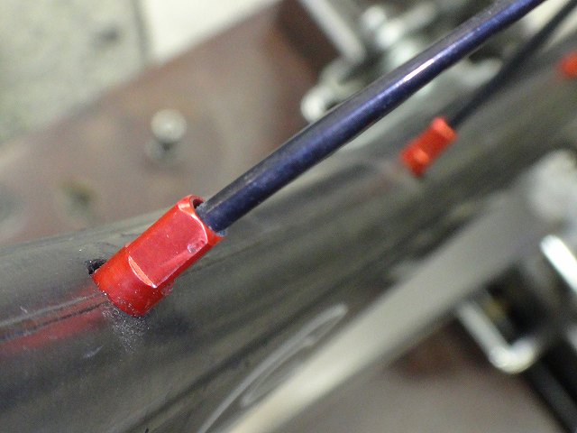
On the Assault rim, the outer holes are centered on both sides — there's no hole offset.
I think this is to prevent the tubeless hump (the bead seat ridge)
from getting cut by the rim holes.
There's an example of someone with hole offset cutting the hump (here).
Though to be fair, that case involved an offset rim so it couldn't be helped.
As for the inner holes, the holes themselves are centered,
but the hole orientation seems to be subtly alternating left-right,

and in several spots the spoke angle got pretty tight.
It's not happening at every spot, so the hole orientation isn't extremely directional.
But if the hole drilling had been done right, it probably wouldn't have happened.
Alternatively, since the Reynolds stock wheels start with correct hole orientation
on the inner rim, the first wheel build might have set a pattern,
and the second build went the opposite direction,
which could explain why this showed up in more places.
I decided this didn't warrant a complete disassembly,
so I did a partial breakdown and adjustment by loosening the nipples.
It's built.
And I did the spoke tensioning.
I did all the wheel adjustment work right in front of the customer
while explaining the fine points,
and for the spoke tensioning, I showed the difference between
wrapping-style and knotting-style tensioning with a live demo,
and had them confirm the difference with and without tensioning.
Also unrelated to this, but they wanted to see the midrill treatment,
so I demonstrated it on a nomlab wheel #5 rim before treatment.
And separately, today when handing over nomlab wheel #2,
I was explaining tubular tire installation, how to fold up spare tubular tape
(not a typo), how to fold spare tires using "under-saddle fold" and "jersey pocket fold,"
the difference between "relay valve" and "cap valve" extenders,
and the differences in carbon rim brake shoe properties,
when they asked about midrill treatment,
so I brought out another nomlab wheel #5 rim and did another demo.
Tomorrow's wheel build is gonna be juuust a little bit easier!
It doesn't fall under the usual category, but
it actually took even more work time than that.
A customer brought in a Reynolds Assault rear wheel.
The person who brought it is the owner, but a friend had rebuilt it,
and they wanted me to do the spoke tensioning and solder the spokes.
Our shop gets customers from far away pretty often,
but this customer came directly by express bus from the Kanto region.
They're taking the bullet train back home.
After the rebuild, the setup is:
Evolight hub 24-hole black Compe / Aerolight 46-spoke lacing.
The spoke weight distribution is almost the same as half-Compe
(Compe/CX-RAY), so it's basically the same spec.
As I've mentioned before,
when I only do spoke tensioning on a wheel I didn't build myself,
if the truing accuracy or tension is below my acceptable standard,
I do corrective adjustments, and if even that doesn't reach my standard,
I won't do the work.
I know that sounds pretty arrogant to say,
but this builder seems to be asking "How does this look? Check it out!"
so I'll be frank about it.
Almost no lateral runout, dead center,
and not a single stripped nipple — that was the condition.
There are pseudo-pro shops out there that touch stock Reynolds wheels
under the guise of inspection, then shift the center and strip nipples
(→here),
so for amateur work, this was excellent.
There was just a faint amount of radial runout that hadn't been completely corrected.
I had the customer check the amount of radial runout before and after the work.
But that was pretty minor stuff—
nothing you'd actually feel while riding.
As for spoke tension, there was still room to tighten.
You can't just keep tightening more and more, but it could still go tighter.
This is where it gets tricky, I think.
I showed the customer three stages of values on our Hozan tension meter
(H1ST — Hozan's First Spoke Tension reading).
For the actual work, first I loosened the non-drive side nipples exactly 3 full turns.
From there, I tightened the drive side
and ended up tightening it by about 2 turns total.
The first phase of that was 1 turn per spoke.
At the same time as tightening the drive side, I also made fine radial runout corrections.
Then I tightened the non-drive side nipples again by 3 full turns.
Since I'd tightened the drive side, the wheel center had shifted toward the drive side.
From that point, until the wheel center came back into true,
I could keep tightening the non-drive side one-directionally —
that's what I call the "tightening bonus."
The H1ST reading on the drive side before the work (A) when the center was dead-on,
and the H1ST reading on the drive side at the point of greatest center deviation
(from non-drive minus 3 turns to drive plus about 2 turns) (B)
were roughly the same, or B was slightly higher,
and after I brought the center back true with non-drive side tightening (before soldering),
the minimum value among the 12 spoke tension readings on the drive side (C)
was higher than the maximum value among the 12 spoke readings before work,
with no overlap. I had the customer confirm this.
The customer said "the range changed," but
I prefer the word "transformed."
Even with just non-drive side tightening, tension increases throughout the wheel,
so the drive side spoke tension increases too.
I'll add a diagram for H1ST values A, B, C later.
Edit: Since this got long, I drew it here.

Despite using right-handed 46-spoke Italian lacing,
the hole drilling was done wrong, so the valve hole ended up
in the middle of the final crossing pair.
That itself isn't a big deal, but building it with reverse hole orientation was the problem.
On the Assault rim, the outer holes are centered on both sides — there's no hole offset.
I think this is to prevent the tubeless hump (the bead seat ridge)
from getting cut by the rim holes.
There's an example of someone with hole offset cutting the hump (here).
Though to be fair, that case involved an offset rim so it couldn't be helped.
As for the inner holes, the holes themselves are centered,
but the hole orientation seems to be subtly alternating left-right,
and in several spots the spoke angle got pretty tight.
It's not happening at every spot, so the hole orientation isn't extremely directional.
But if the hole drilling had been done right, it probably wouldn't have happened.
Alternatively, since the Reynolds stock wheels start with correct hole orientation
on the inner rim, the first wheel build might have set a pattern,
and the second build went the opposite direction,
which could explain why this showed up in more places.
I decided this didn't warrant a complete disassembly,
so I did a partial breakdown and adjustment by loosening the nipples.
It's built.
And I did the spoke tensioning.
I did all the wheel adjustment work right in front of the customer
while explaining the fine points,
and for the spoke tensioning, I showed the difference between
wrapping-style and knotting-style tensioning with a live demo,
and had them confirm the difference with and without tensioning.
Also unrelated to this, but they wanted to see the midrill treatment,
so I demonstrated it on a nomlab wheel #5 rim before treatment.
And separately, today when handing over nomlab wheel #2,
I was explaining tubular tire installation, how to fold up spare tubular tape
(not a typo), how to fold spare tires using "under-saddle fold" and "jersey pocket fold,"
the difference between "relay valve" and "cap valve" extenders,
and the differences in carbon rim brake shoe properties,
when they asked about midrill treatment,
so I brought out another nomlab wheel #5 rim and did another demo.
Tomorrow's wheel build is gonna be juuust a little bit easier!