I'd like to start by discussing the rear wheel of the Cannondale AI that I built the other day,
but first.
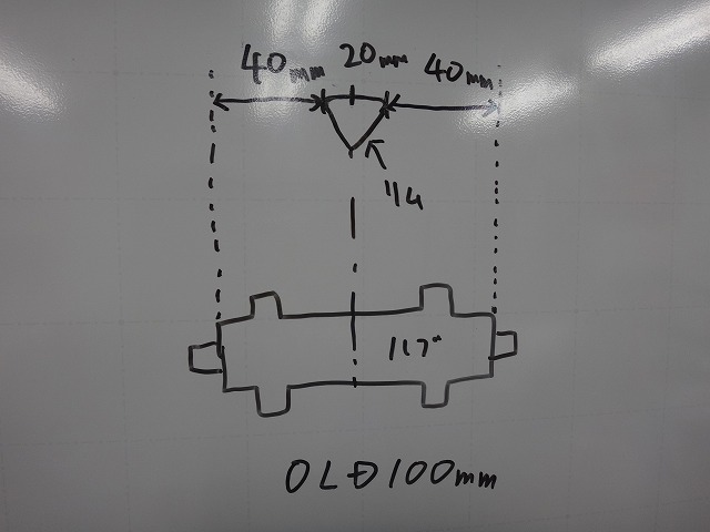
Let me talk about the relationship between how much the rim is shifted and the gap between the centering gauge and the dropouts.
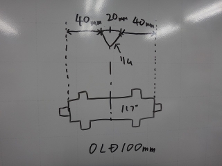
I'll use a rim brake front wheel with an over-locknut dimension of 100mm.
Since there are idiots who get confused without imagining a concrete rim width, I'm setting it to 20mm.
In this case, if the wheel is properly centered,
the distance from both dropouts (the surface where the gauge contacts) to the rim
is 40mm on both the left and right.
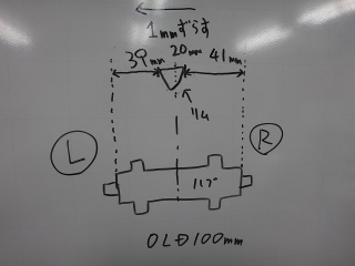
From there, I shifted the rim 1mm to the left.
At this point, the distance from the left dropout to the rim becomes 40−1=39mm,
and the distance from the right dropout to the rim becomes 40+1=41mm.
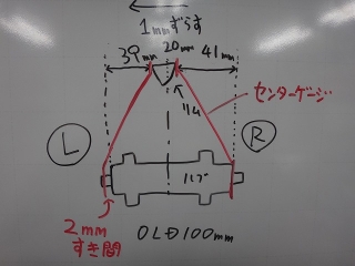
So, if I take the measurement from the side where the dropout-to-rim distance is greater (41mm side)
and apply it to the rim on the closer side (39mm side),
the gap between the dropout and rim becomes 2mm.
The centering deviation image I always show in articles is this gap.
In other words, "when a rim is shifted by Xmm, the deviation visible on the centering gauge is 2Xmm."
When I first built a rear wheel for a Cannondale AI frame,
I was told to "shift the rim 6mm,"
so I made the distance between the left dropout and rim 6mm (→see here).
I corrected this later.
So that idiot at the beginning is me.

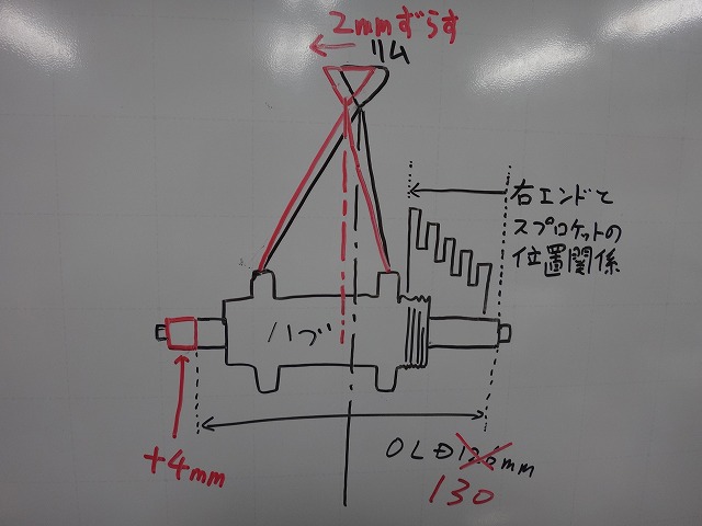
This is another topic. When modifying a boss hub with an over-locknut dimension of 126mm
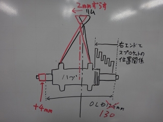
to 130mm, I extend only the left side by 4mm.
I also replace the hub axle if necessary.
You must not change the right side dimension.
It will change the derailleur position setting.
If you add 2mm on both sides, the spoke angle of the wheel doesn't change,
but the derailleur position setting does change.
If you add 4mm only on the right side, the dish becomes dramatically worse.
When extending the over-locknut dimension by 4mm on only one side,
the rim displacement is 2mm.
The Cannondale AI
offsets the rim by 6mm
to reduce the dish on the rear hub.
Compared to a general frame,
the difference in spoke tension between left and right certainly decreases,
but since we're not using a hub with an exceptionally wide flange for a general rear hub,
there's no dramatic improvement in lateral stiffness.
While we can't retroactively widen the flange,
there are various ways to mitigate the difference in spoke tension (or rather, deformation),
so my wish is for wider hub flanges even if the dish becomes tighter.
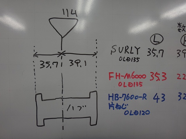
The left and right flange widths written in the diagram above
are measurements I personally took from the rear hub that came with the Cannondale Topstone complete bike.
The flange width I measure is the width to the outer edge of the flange, which is the same as Shimano's method.
This outer-to-outer flange width is around 53mm for 11S or 12S hubs if it's on the narrow side,
and around 58mm if it's on the wide side
(with BOOST spec there are also 62-63mm ones).
On the Cannondale hub the other day,
35.7 + 21.6 = 57.3mm,
so it wasn't particularly narrow,
but it was a standard rear hub dimension rather than an extreme proprietary specification.
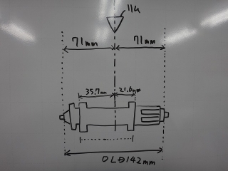
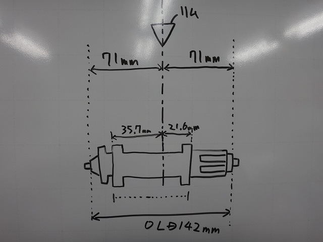
The diagram above shows the rim position when installed on a normal frame,
and if you divide the over-locknut dimension of 142mm at the rim center,
both left and right become 71mm,
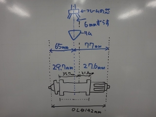
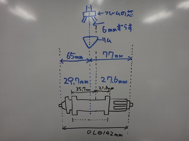
but the AI approach is to use this hub's dimensions as
left side 71−6=65mm and right side 71+6=77mm.
The rim center and frame center are located at the 65:77mm position.
Up to this point, I've written almost the same story before (→see here).
Since this article is about offset rims, I'll continue on that topic.
When this hub is used on a normal frame, the flange width of 57.3mm breaks down as
left flange width : right flange width = 35.7:21.6mm,
but when assembled as a wheel for the AI frame, it becomes 29.7:27.6mm.
The dish is significantly reduced.
This is with a regular rim, not an offset rim, and
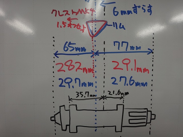
the Stanz Crest MK4 that I recently used for a rebuild
is an offset rim, unlike the previous model MK3 (now discontinued).
It just happened to be offset when searching for a light aluminum rim,
and in this case, the offset is unwanted for me.
If the Crest MK3 were still being sold alongside it,
or if the wholesaler had inventory remaining, I would have sourced the MK3.
In this hub case, even when used on an AI frame,
it has reverse dish with a narrow right flange.
So I don't use the offset rim in reverse orientation.
The Crest MK4 has a dish amount of 1.5mm, so
when used in the standard offset rim orientation,

↑it looks like this.
The left flange width becomes −1.5mm and the right flange width becomes +1.5mm,
so the flange width becomes 28.2:29.1mm with reverse dish.
However, the left-right difference in flange width itself has decreased from 2.1mm to 0.9mm.
You might think, "If the rim moved 1.5mm, it's strange that the flange difference is 1.2mm,"
but the original positive dish of 2.1mm became a reverse dish of 0.9mm due to the offset rim,
so the difference between 2.1mm and −0.9mm is 3mm.
Treating positive dish as positive and reverse dish as negative,
comparing absolute values across the zero boundary gives this result.
When the rim shifts by 1.5mm, the flange difference becomes 3mm compared to the original state,
which is the same logic as the opening discussion.
You just swap out "distance from the left dropout to the rim..." with
"distance from the left flange outer edge to the rim..."
Even though it's reverse dish, since it's about the amount of dish
occasionally seen on dynamo front hubs,
the AI rear wheel I built recently uses equal-diameter, equal-count left and right spokes.
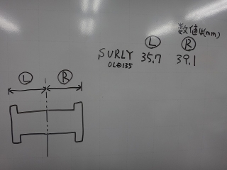
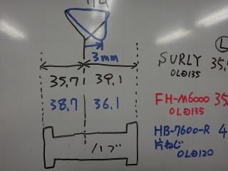
Next, about the rear wheel from the previous article.
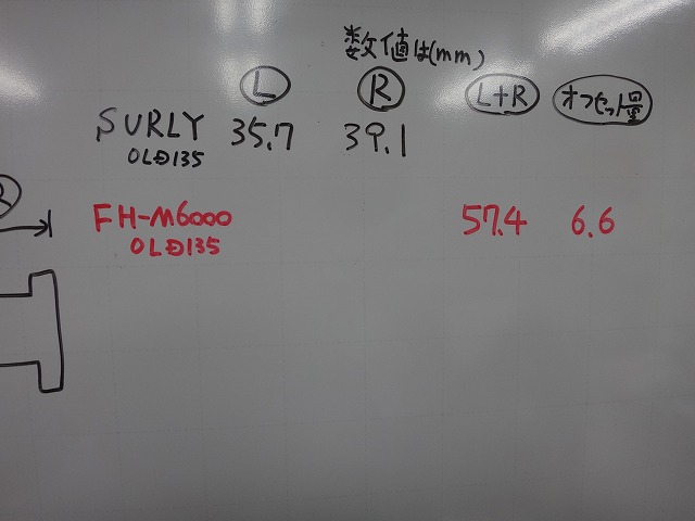
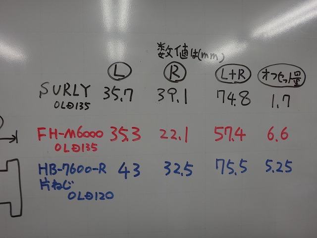
The hub is a Surly
with an over-locknut dimension of 135mm in quick-release specification,
one side has a fixed sprocket carrier and the other side has a disc rotor carrier.
The flange width numbers are my personal measurements.
It's a reverse-dish hub with the right flange wider.
Don't worry about the left diagram appearing to be divided roughly in the middle—it just means this is the hub dimension in that area.

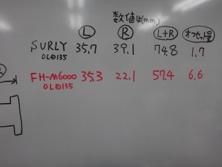
As another 135mm wide quick-release hub,
I've added the published dimensions of Shimano Deore FH-M6000.
I chose Deore because XT and XTR only have through-axle hubs.
As I mentioned before, Shimano's published values are measured the same way as mine,
so the numbers can be compared as being measured the same way.
This is something I've written before, but
Shimano should just list the left and right flange widths directly in the catalog,
yet they only provide flange width and offset amount.
You can calculate the left and right flange widths by adding and subtracting the offset amount to/from half the flange width.
I calculated it.
While I'm at it, I've also written the Surly hub in Shimano-style notation.
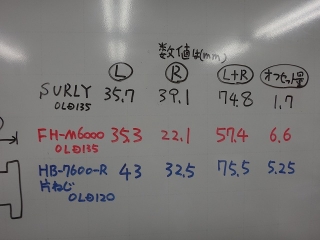
Additionally, I've added the dimensions of the Dura-Ace Track single-threaded side
large-flange rear hub.
The Deore hub has a long free body section so the right flange is narrow,
Surly's hub has an over-locknut dimension 15mm wider than Dura-Ace Track yet
similar flange width, probably because the disc rotor carrier takes up space,
Surly's small offset amount is excellent... but
wait, that's reverse dish!, etc.—you can learn various things.

I've added the rim to the left diagram above.
I've also redrawn the line dividing the flange width, offset from center.
According to my wholesaler's literature, the AL22W rim offset specification is
supposedly 3mm offset, but it doesn't look that much,
so I investigated.
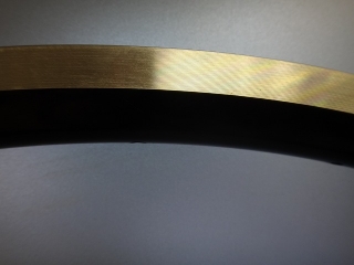
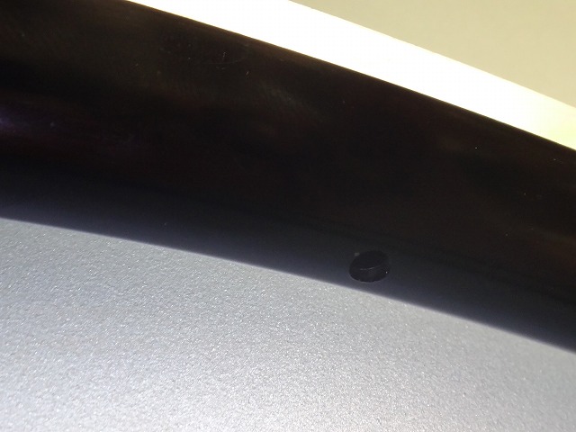
For the AL22W offset rim with a rim brake braking zone that sits flat on a glass surface plate,

I measured the left and right distances from the rim edge to the hole edge
and the hole diameter.
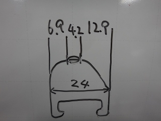
Based on my measurements, the breakdown is like this.
The three add up to 24.0mm, and the rim's published outer width is also 24mm,
but when I measure the rim's outer width directly, it's around 24.2mm for some reason.
The rim hole diameter also comes out as 4.3mm for some holes,
so there's 0.1mm level error in all parts.
Since there was left and right hole runout on the rim holes,
I averaged the right hole runout and left hole runout measurements respectively.
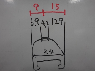
If I set the rim hole diameter to zero,
or calculate the distance from the rim edge to the hole center,
I get 9:15mm.
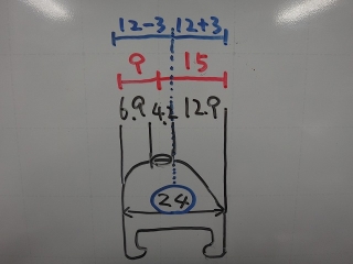
This is ±3mm from the rim center of 12mm,
so the published value of 3mm offset was correct.
The fact that the value came out to exactly 3.0mm is not because
I arbitrarily adjusted the decimal places.
I myself thought that even if 3mm offset was true,
measurement and calculation results would be 2.9mm or 3.2mm or something,
never coming out to exactly 3.0mm.
For the rear wheel from the previous article,
I used the offset rim in reverse orientation
to flip the reverse dish.
From 35.7−39.1=−3.4mm
to 38.7−36.1=2.6mm,
so the dish changed by 6mm with a 3mm rim hole shift.
The absolute value of the dish amount decreased by 0.8mm.
The final state including the rim offset amount written in Shimano style would be
flange width 74.8mm, offset amount 1.3mm.
This is almost zero dish, so for a new wheel build I could do a 6-spoke-hole build,
but since there was a condition to reuse spokes as much as possible,
I did a 4-6 build.
As a result, the right side (small cog side) has higher tension,
but compared to a normal freewheel rear wheel with equal diameter, equal count, equal number left and right spokes,
the spoke tension (and deformation) left-right difference is smaller,
and while it's quite strange that
a normal rear wheel's non-freewheel side spokes show clearly less deformation (stiffer)—
(looking at you, Rohloff disc brake rear wheel)
I thought having the cog side a bit stiffer is fine.
If it seemed too bad while building,
I would consult with the customer and change the build method.
The "offset amount" value in Shimano's catalog for hubs
is convenient as a concept because you can compare it directly with rim offset amount.
However, it's rare to think about how to minimize the absolute value of offset amount when
building wheels with AI-spec frames or reverse-dish hubs and offset rims,
and in such cases I investigate on my own anyway,
so regarding the published values for left and right flange widths, I really would prefer if they just published the numbers themselves.
For AI frames, non-offset rims are less hassle.
If it's not an offset rim, even if there's still slight dish remaining,
you don't need to worry about whether reverse dish might occur with hubs that have flanges unrelated to Cannondale
and are extremely narrow
(especially narrow on the left flange side), since
flipping the rim won't change anything anyway.
but first.
Let me talk about the relationship between how much the rim is shifted and the gap between the centering gauge and the dropouts.
I'll use a rim brake front wheel with an over-locknut dimension of 100mm.
Since there are idiots who get confused without imagining a concrete rim width, I'm setting it to 20mm.
In this case, if the wheel is properly centered,
the distance from both dropouts (the surface where the gauge contacts) to the rim
is 40mm on both the left and right.

From there, I shifted the rim 1mm to the left.
At this point, the distance from the left dropout to the rim becomes 40−1=39mm,
and the distance from the right dropout to the rim becomes 40+1=41mm.

So, if I take the measurement from the side where the dropout-to-rim distance is greater (41mm side)
and apply it to the rim on the closer side (39mm side),
the gap between the dropout and rim becomes 2mm.
The centering deviation image I always show in articles is this gap.
In other words, "when a rim is shifted by Xmm, the deviation visible on the centering gauge is 2Xmm."
When I first built a rear wheel for a Cannondale AI frame,
I was told to "shift the rim 6mm,"
so I made the distance between the left dropout and rim 6mm (→see here).
I corrected this later.
So that idiot at the beginning is me.

This is another topic. When modifying a boss hub with an over-locknut dimension of 126mm
to 130mm, I extend only the left side by 4mm.
I also replace the hub axle if necessary.
You must not change the right side dimension.
It will change the derailleur position setting.
If you add 2mm on both sides, the spoke angle of the wheel doesn't change,
but the derailleur position setting does change.
If you add 4mm only on the right side, the dish becomes dramatically worse.
When extending the over-locknut dimension by 4mm on only one side,
the rim displacement is 2mm.
The Cannondale AI
offsets the rim by 6mm
to reduce the dish on the rear hub.
Compared to a general frame,
the difference in spoke tension between left and right certainly decreases,
but since we're not using a hub with an exceptionally wide flange for a general rear hub,
there's no dramatic improvement in lateral stiffness.
While we can't retroactively widen the flange,
there are various ways to mitigate the difference in spoke tension (or rather, deformation),
so my wish is for wider hub flanges even if the dish becomes tighter.
The left and right flange widths written in the diagram above
are measurements I personally took from the rear hub that came with the Cannondale Topstone complete bike.
The flange width I measure is the width to the outer edge of the flange, which is the same as Shimano's method.
This outer-to-outer flange width is around 53mm for 11S or 12S hubs if it's on the narrow side,
and around 58mm if it's on the wide side
(with BOOST spec there are also 62-63mm ones).
On the Cannondale hub the other day,
35.7 + 21.6 = 57.3mm,
so it wasn't particularly narrow,
but it was a standard rear hub dimension rather than an extreme proprietary specification.
The diagram above shows the rim position when installed on a normal frame,
and if you divide the over-locknut dimension of 142mm at the rim center,
both left and right become 71mm,
but the AI approach is to use this hub's dimensions as
left side 71−6=65mm and right side 71+6=77mm.
The rim center and frame center are located at the 65:77mm position.
Up to this point, I've written almost the same story before (→see here).
Since this article is about offset rims, I'll continue on that topic.
When this hub is used on a normal frame, the flange width of 57.3mm breaks down as
left flange width : right flange width = 35.7:21.6mm,
but when assembled as a wheel for the AI frame, it becomes 29.7:27.6mm.
The dish is significantly reduced.
This is with a regular rim, not an offset rim, and
the Stanz Crest MK4 that I recently used for a rebuild
is an offset rim, unlike the previous model MK3 (now discontinued).
It just happened to be offset when searching for a light aluminum rim,
and in this case, the offset is unwanted for me.
If the Crest MK3 were still being sold alongside it,
or if the wholesaler had inventory remaining, I would have sourced the MK3.
In this hub case, even when used on an AI frame,
it has reverse dish with a narrow right flange.
So I don't use the offset rim in reverse orientation.
The Crest MK4 has a dish amount of 1.5mm, so
when used in the standard offset rim orientation,
↑it looks like this.
The left flange width becomes −1.5mm and the right flange width becomes +1.5mm,
so the flange width becomes 28.2:29.1mm with reverse dish.
However, the left-right difference in flange width itself has decreased from 2.1mm to 0.9mm.
You might think, "If the rim moved 1.5mm, it's strange that the flange difference is 1.2mm,"
but the original positive dish of 2.1mm became a reverse dish of 0.9mm due to the offset rim,
so the difference between 2.1mm and −0.9mm is 3mm.
Treating positive dish as positive and reverse dish as negative,
comparing absolute values across the zero boundary gives this result.
When the rim shifts by 1.5mm, the flange difference becomes 3mm compared to the original state,
which is the same logic as the opening discussion.
You just swap out "distance from the left dropout to the rim..." with
"distance from the left flange outer edge to the rim..."
Even though it's reverse dish, since it's about the amount of dish
occasionally seen on dynamo front hubs,
the AI rear wheel I built recently uses equal-diameter, equal-count left and right spokes.

Next, about the rear wheel from the previous article.
The hub is a Surly
with an over-locknut dimension of 135mm in quick-release specification,
one side has a fixed sprocket carrier and the other side has a disc rotor carrier.
The flange width numbers are my personal measurements.
It's a reverse-dish hub with the right flange wider.
Don't worry about the left diagram appearing to be divided roughly in the middle—it just means this is the hub dimension in that area.
As another 135mm wide quick-release hub,
I've added the published dimensions of Shimano Deore FH-M6000.
I chose Deore because XT and XTR only have through-axle hubs.
As I mentioned before, Shimano's published values are measured the same way as mine,
so the numbers can be compared as being measured the same way.
This is something I've written before, but
Shimano should just list the left and right flange widths directly in the catalog,
yet they only provide flange width and offset amount.
You can calculate the left and right flange widths by adding and subtracting the offset amount to/from half the flange width.

I calculated it.
While I'm at it, I've also written the Surly hub in Shimano-style notation.
Additionally, I've added the dimensions of the Dura-Ace Track single-threaded side
large-flange rear hub.
The Deore hub has a long free body section so the right flange is narrow,
Surly's hub has an over-locknut dimension 15mm wider than Dura-Ace Track yet
similar flange width, probably because the disc rotor carrier takes up space,
Surly's small offset amount is excellent... but
wait, that's reverse dish!, etc.—you can learn various things.
I've added the rim to the left diagram above.
I've also redrawn the line dividing the flange width, offset from center.
According to my wholesaler's literature, the AL22W rim offset specification is
supposedly 3mm offset, but it doesn't look that much,
so I investigated.

For the AL22W offset rim with a rim brake braking zone that sits flat on a glass surface plate,
I measured the left and right distances from the rim edge to the hole edge
and the hole diameter.

Based on my measurements, the breakdown is like this.
The three add up to 24.0mm, and the rim's published outer width is also 24mm,
but when I measure the rim's outer width directly, it's around 24.2mm for some reason.
The rim hole diameter also comes out as 4.3mm for some holes,
so there's 0.1mm level error in all parts.
Since there was left and right hole runout on the rim holes,
I averaged the right hole runout and left hole runout measurements respectively.

If I set the rim hole diameter to zero,
or calculate the distance from the rim edge to the hole center,
I get 9:15mm.

This is ±3mm from the rim center of 12mm,
so the published value of 3mm offset was correct.
The fact that the value came out to exactly 3.0mm is not because
I arbitrarily adjusted the decimal places.
I myself thought that even if 3mm offset was true,
measurement and calculation results would be 2.9mm or 3.2mm or something,
never coming out to exactly 3.0mm.

For the rear wheel from the previous article,
I used the offset rim in reverse orientation
to flip the reverse dish.
From 35.7−39.1=−3.4mm
to 38.7−36.1=2.6mm,
so the dish changed by 6mm with a 3mm rim hole shift.
The absolute value of the dish amount decreased by 0.8mm.
The final state including the rim offset amount written in Shimano style would be
flange width 74.8mm, offset amount 1.3mm.
This is almost zero dish, so for a new wheel build I could do a 6-spoke-hole build,
but since there was a condition to reuse spokes as much as possible,
I did a 4-6 build.
As a result, the right side (small cog side) has higher tension,
but compared to a normal freewheel rear wheel with equal diameter, equal count, equal number left and right spokes,
the spoke tension (and deformation) left-right difference is smaller,
and while it's quite strange that
a normal rear wheel's non-freewheel side spokes show clearly less deformation (stiffer)—
(looking at you, Rohloff disc brake rear wheel)
I thought having the cog side a bit stiffer is fine.
If it seemed too bad while building,
I would consult with the customer and change the build method.
The "offset amount" value in Shimano's catalog for hubs
is convenient as a concept because you can compare it directly with rim offset amount.
However, it's rare to think about how to minimize the absolute value of offset amount when
building wheels with AI-spec frames or reverse-dish hubs and offset rims,
and in such cases I investigate on my own anyway,
so regarding the published values for left and right flange widths, I really would prefer if they just published the numbers themselves.
For AI frames, non-offset rims are less hassle.
If it's not an offset rim, even if there's still slight dish remaining,
you don't need to worry about whether reverse dish might occur with hubs that have flanges unrelated to Cannondale
and are extremely narrow
(especially narrow on the left flange side), since
flipping the rim won't change anything anyway.