Finally got here!
What I'm about to write is close to my final conclusion.
There's still plenty more material, but I've been writing about inpokes and all sorts of things up to now just to get to this point. As usual, this is incredibly long.
Last time I wrote about correcting spoke tension differential in rear wheels when viewed from the front-to-back direction.
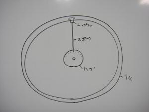
The answer was offset rims and high-low flanges, but today's about viewing the wheel from left-to-right.
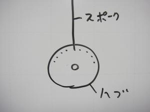
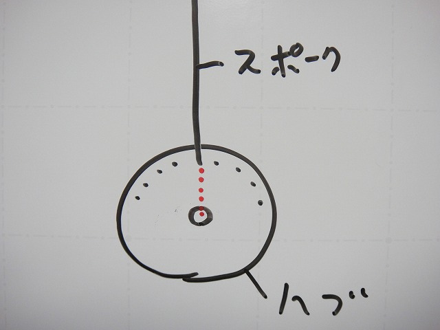
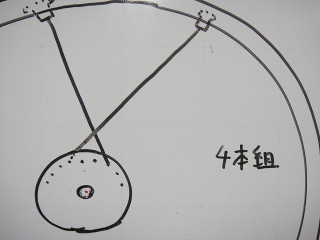
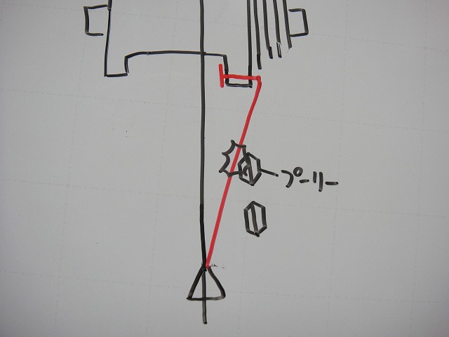
In this diagram I've drawn inpoke radial spokes, but
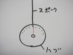
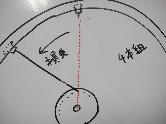
with radial lacing, the spoke's extension line when viewed from the side
(the red dashed line in the diagram above) passes through the hub center.
I'll call this the "radial line" from now on.
You can also think of it as a line segment derived from a circle's radius.
The term "radial line" exists in amateur radio too, but
it's completely unrelated. It's my own made-up term.
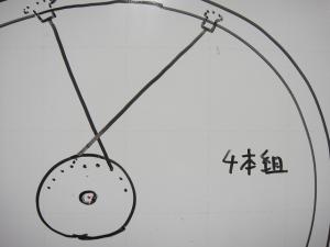
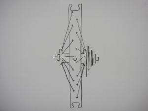
Next, consider a 4-cross lacing made with inpokes and outpokes.
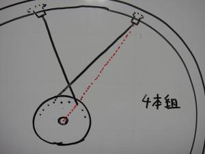
Here's what the radial line looks like from the inpoke hub holes:

It's hard to see, so I removed the outpokes and left just the inpokes.
The spoke leaving the hub pulls the rim most directly
when the spoke overlaps the radial line (radial lacing).
From there, as tangential lacing increases in crossing number and the spoke
deviates further from the radial line, spoke tension loss occurs.
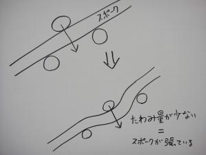
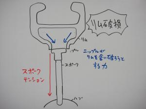
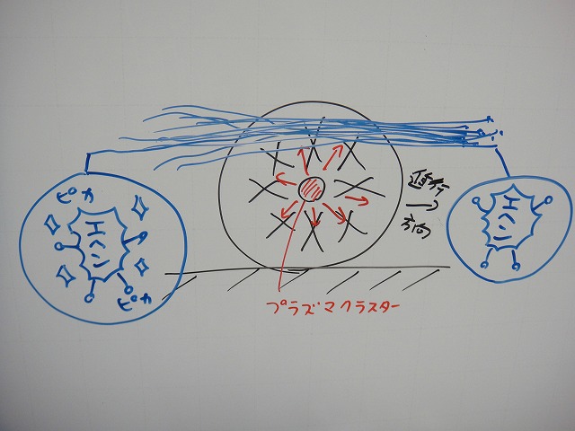
Spoke tension (how taut the spoke feels) can be measured
by observing deflection using the method shown in the diagram above.
Thicker spokes deform less (deflect less) so
it's not technically a unique measurement method, but
since there's no other way, this is how we measure it.
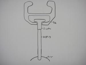
↑This diagram has the rim and hub at 90° right angles, which is weird,
but I ask you not to nitpick about it.
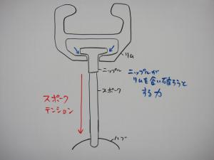
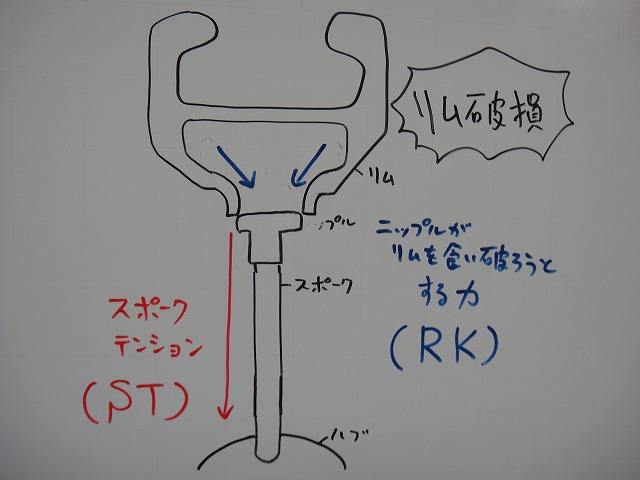
Tightening the nipple increases spoke tension.
(shown by the red arrows in the diagram above)
At the same time, the nipple shank bites into the rim.
(shown by the blue arrows in the diagram above)
If we keep raising spoke tension endlessly from here,
one of the four components—rim, nipple, spoke, and hub—
will break and the wheel becomes unusable.
If the hub is weak, the hub flange will tear off.
I haven't seen this happen while building, but
there are actually documented cases of it tearing after time has passed on a wheel laced radially.
This is the least likely of the four to happen.
If the spoke is weak, it breaks at the neck.
This rarely happens while building either, but spoke breakage from fatigue does occur during wheel use.
When truing a well-used wheel, sometimes a spoke will snap at the neck the moment you tighten the nipple.
This is the most likely of the four to happen.
If the nipple is weak, the rim-facing shank breaks in a crack that runs all the way around,
causing the spoke to pull out from the rim.
This is the second most common after spoke breakage.
Laypeople often call this "spoke breakage" too.
Since there's damage in the spoke area that needs repair, there's nothing wrong with that terminology.
Nipples come in brass and aluminum, and lightweight aluminum is thought to be more prone to this.
Aluminum nipples do strip their corners easily while building, that's true,
but as for whether their tensile strength is weaker than brass... I'm not so sure.
From my personal experience, aluminum might actually be stronger once it's built up.
My theoretical basis for this is thin, so I won't state it as fact.
If aluminum really is stronger, that would mean (for users, not for wheel builders)
you could achieve weight savings with zero risk.
If the rim is weak, it breaks as shown in the diagram above.
(Though the diagram's probably not visible after all this text)
This can happen with age from use, but rims with low tensile strength at the spoke holes
can experience this even while building.
Carbon rims are supposedly weaker than aluminum rims in this regard,
but lately there are rims that can handle spoke tension as high or higher than aluminum,
so you can't generalize.
The reason rim manufacturers specify an upper limit for spoke tension
is to make this less likely to happen.

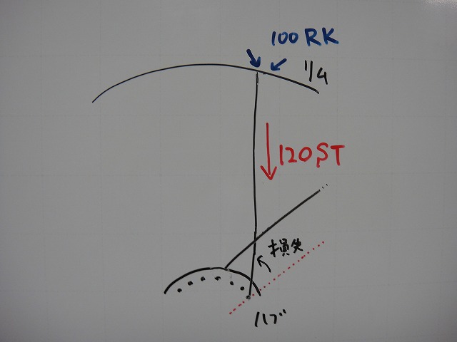
Here I'll express spoke tension as ST,
and the force trying to bite through the rim as RK.
SpokeTension for ST and
RimKui-破る (biting through) for RK.
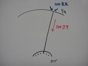
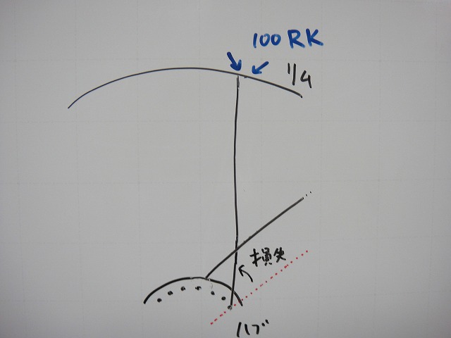
Going back to a diagram like the one at the start, when a spoke is tensioned to 100 ST in radial lacing,
let's say 100 RK of pull is generated on the rim.
Manufacturers are concerned about RK regarding rim breakage,
but RK can't be measured (maybe specialized testing facilities could),
so normally we measure ST using the method I mentioned earlier.
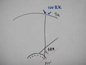
Next, consider achieving 100 RK of pull with 4-cross lacing.
4-cross spokes pull in a direction off the radial line,
so there's a loss of pulling force. To reach 100 RK with that loss,

you need to pull with more than 100 ST to achieve 100 RK.
The diagram says 120 ST, but that's not the actual precise value.
It's definitely more than 100 ST, but it's roughly that range.
If a manufacturer says "don't build higher than 100 ST," we'd build 4-cross with 100 ST as the upper limit,
but the RK at that point would probably be around 80 RK.

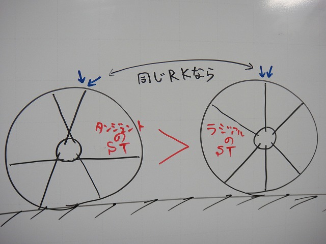
What's important here is: With the same RK, radial lacing achieves lower spoke tension than tangential lacing.
This whole section of text, I've just been trying to say that one thing.
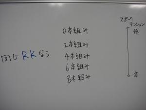
RK is directly related to wheel vertical stiffness, but since rim manufacturers specify the upper limit as ST,
when ST is tensioned to the manufacturer's upper limit,
RK is highest with 0-cross (radial lacing).
"Radial lacing makes a stiffer wheel vertically" is no myth or legend.
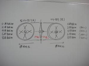
From there, moving to 2→4→6→8-cross as tangential lacing increases,
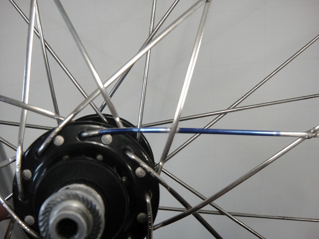
the RK gain per ST decreases due to the loss from deviation from the radial line.
↑The spokes colored blue in this image are 8-cross inpokes,
and they're nearly perpendicular to the radial line.
Close to the tangent to the circle (hub flange). Tangential lacing's "tangent" means
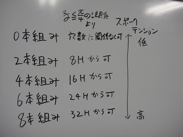
tangent line, so this is literally tangent lacing.
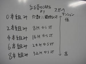
When doing 0 through 8-cross, here's what hub hole counts make each possible.
I'll use y≦4/x. Really handy, this.

When viewing a wheel from front-to-back, I usually draw it from straight behind,
but this time let's say I'm viewing from straight above.
The eyes that look sharp... well, yes.
But that's not related to Sharp the company.
If Sharp ever designed a bicycle wheel, they'd definitely
add a Plasmacluster to it.

If a wheel with a Plasmacluster-generating hub rides along
and we blow a cough bug from the front,
thanks to the negative ion effect,
it becomes a beautiful cough bug.
Never mind the cough bug (why did I even write that?),
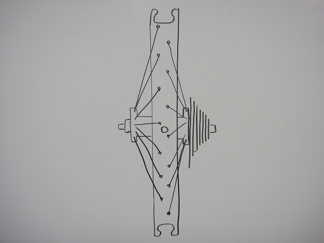
let me look at a wheel without a tire from above.
Let's say the valve hole is straight up.
Let me take this wheel and slice it open with the magic knife from the Inpoke Part 1 entry
(→here).
I'll slice carefully to avoid the rim holes,
and cut the hub straight in half.
The sprocket side makes it clear which direction is forward.
Both sides being radial lacing is just for visibility, so let's ignore that.
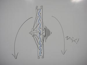
This time I'm not flattening it, just opening it.
It's like a clam opened to its maximum.

Looking at this from the brake-zone side rather than the rim's cut face
gives you the diagram above.
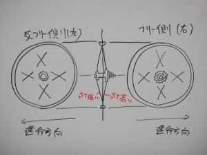
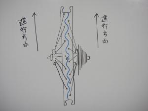
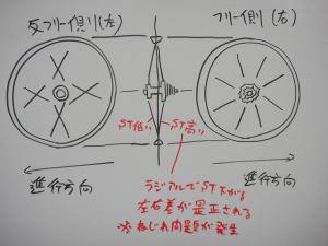
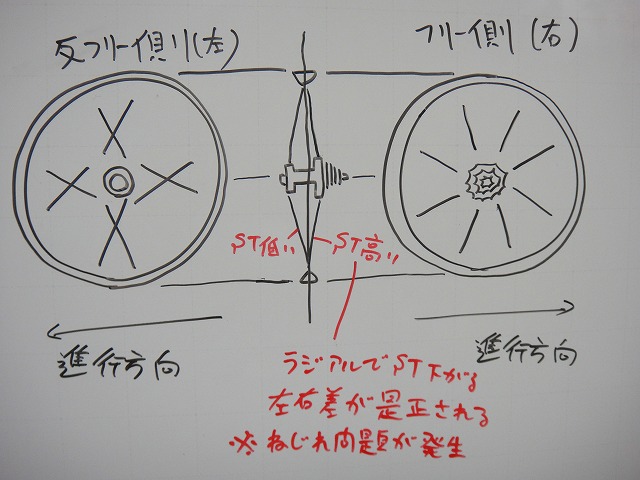
Last time I mentioned that since rear wheels have dish,
the freewheel side has higher spoke tension.
In the diagram above, both sides are tangential lacing.
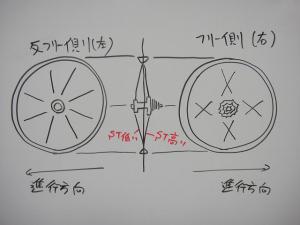
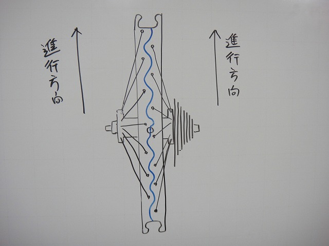
↑If the non-freewheel side is radial laced, it looks like this.
"Both front and rear wheels all radial laced would be maximum advantage in aerodynamics and weight,
but the freewheel side gets intense torsion so let's keep that as tough
tangential lacing to resist twist." That's the thinking.
Many wheel manufacturers do this, but
Easton is the most representative. There are plenty of others.
As I mentioned earlier, radial lacing lowers spoke tension.
Since the non-freewheel side already has lower spoke tension,
lowering it further with radial lacing makes the tension differential even worse.
This is the worst way to lace a wheel from a wheel balance perspective.
My mysterious cosmic carbon wheel has radial lacing on the non-freewheel side, but
that's because of the spoke holes in the rim—
I had no choice but to lace it that way.
When you feel the non-freewheel spokes, they're quite loose.
However, with radial lacing, there's no spoke-to-spoke contact, so
you don't get that creaking noise from contact,
and the weakness on the left doesn't get noticed.
Radial lacing it with inpokes is a subtle act of rebellion.
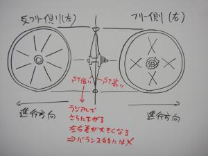
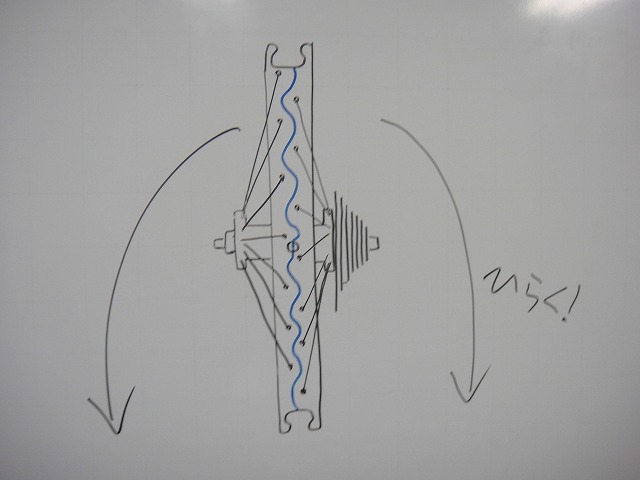
↑What if we try freewheel side radial, non-freewheel side tangential instead?
That would lower the freewheel side tension, making the left-right
balance relatively closer. This is actually the best lacing from a wheel balance perspective. But
Radial lacing is
↑weak to this kind of torsion.
The torsion on the front wheel is only from rim braking,
so it's not a big issue, but on the rear freewheel side, the pedaling-driven
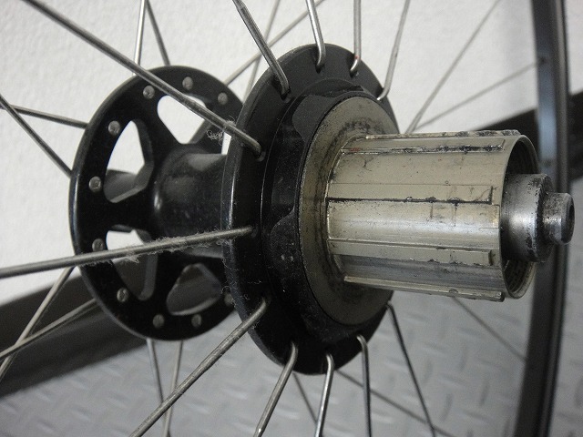
freewheel body twist is extreme, so problems arise.

I've actually tried freewheel-side radial on a hand-built wheel.
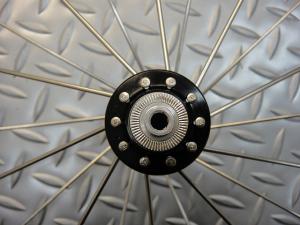
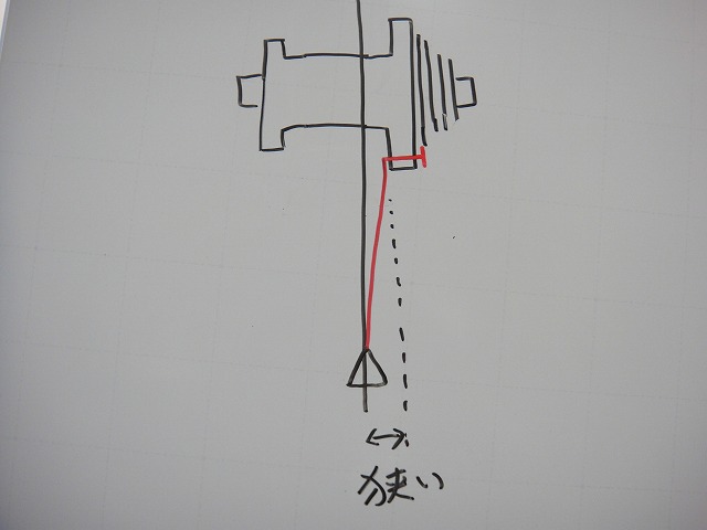
This is inpoke radial, and there's a reason for that.
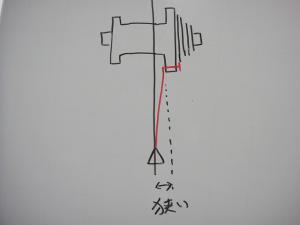
With outpoke radial, it's hard to secure lateral stiffness.
The lateral stiffness calculation is based on where the spoke leaves the hub flange,
and with outpokes that's extremely narrow.
Plus, radial lacing lowering spoke tension means it also resists
the freewheel's intense torsion less well.
In hand-built wheel construction, this outpoke radial
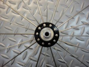
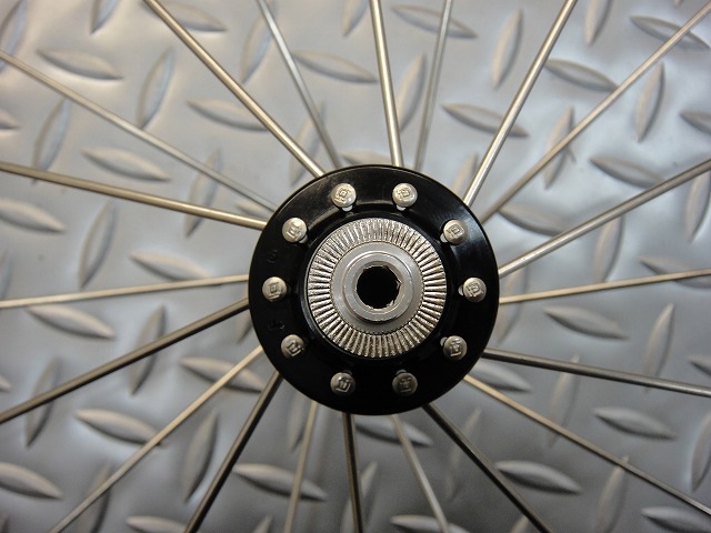
is actually the worst lacing for spoke neck breakage risk.

On the other hand, inpoke radial lacing means
the spokes aren't woven, so lateral spoke spread increases,
which causes the derailleur cage to contact spokes when in low gear—
a problem that easily occurs.
There are workarounds, but even with them, climbing out of the saddle or
hard pedaling on flats can cause contact, so this lacing should be avoided.
2-cross is woven, so
2-cross inpoke → risk of derailleur contact
2-cross outpoke → low lateral stiffness
Neither is recommended.
But freewheel-side radial has major benefits for correcting spoke tension differential. What can we do...
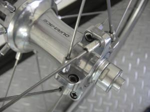
↑"What if we custom-designed the hub and spokes with large-diameter aluminum spokes?"
That incredibly smart wheel is "Kyserium." Kyserium coming in!
Looking at the freewheel body structure, the spokes don't seem to deform from freewheel torsion,
and the aluminum spokes look robust as can be.
For Mavic to think this up in 1999 shows how ahead they were.
This is speculation on my part, but I think Kyserium's starting point was
not "let's make a wheel with aluminum spokes"
but rather "let's make a freewheel-side radial wheel."
The pursuit of structure that could withstand freewheel torsion undaunted
is what led to adopting aluminum spokes, I believe.
~Tangent~
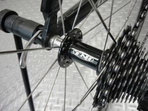
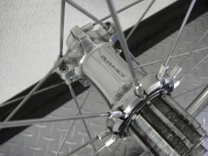
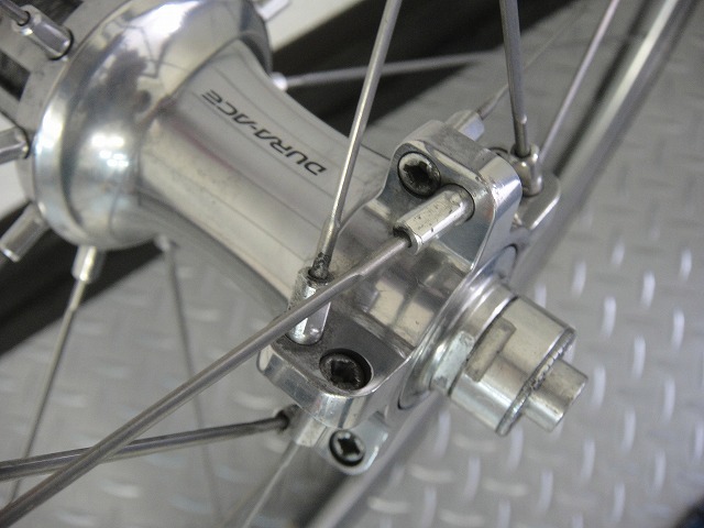
↑This is a 7800-series Dura-Ace pre-built wheel.
Freewheel-side radial. In current models, Zipp wheels and
Mavic's Kyserium Elite have steel spokes with radial lacing, and
with straight spokes' high-tension capability and smart hub design,
they manage steel spokes in freewheel-radial without issues.
This wheel similarly has steel spokes with freewheel-radial.
People often complain that Dura-Ace wheels from this era are "hard to adjust,"
but that has nothing to do with whether the wheel rides well or not, so it doesn't matter.
It's my job to fix them anyway.
The hub internals are a straight copy of Campagnolo's
and the lacing is a straight copy of Kyserium's, but in terms of how thoroughly the wheel logic is thought through,
I think this is Shimano's greatest rear wheel ever made.
After this, they start thinking for themselves, which actually produces mediocre wheels.
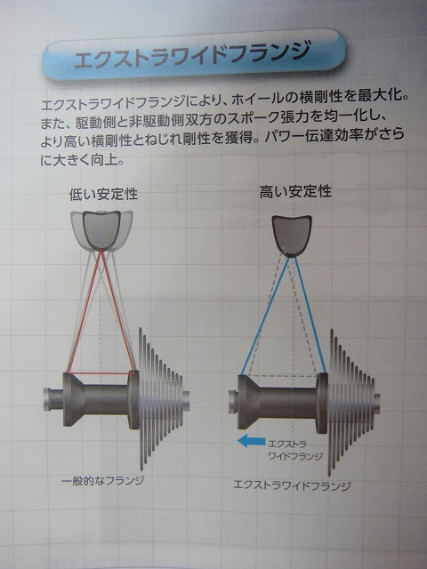
They've pushed the left flange position way out. Clever!
WH-9000 calls itself wide-flange, but the width is about the same as this.

They call it extra-wide-flange, but
even back in the WH-7800 era it was basically extra-wide-flange.
And then they trash-talk their own previous product (WH-7900) from yesterday. That's bold.
~End tangent~
Thanks to T-san for helping photograph these wheels.
That wheel's a masterpiece, so don't you dare sell it.
Freewheel-side radial is only possible with pre-built wheels!
(You can only read this manga in Jump!)
So I want to think about
What I'm about to write is close to my final conclusion.
There's still plenty more material, but I've been writing about inpokes and all sorts of things up to now just to get to this point. As usual, this is incredibly long.

Last time I wrote about correcting spoke tension differential in rear wheels when viewed from the front-to-back direction.
The answer was offset rims and high-low flanges, but today's about viewing the wheel from left-to-right.

In this diagram I've drawn inpoke radial spokes, but
with radial lacing, the spoke's extension line when viewed from the side
(the red dashed line in the diagram above) passes through the hub center.
I'll call this the "radial line" from now on.
You can also think of it as a line segment derived from a circle's radius.
The term "radial line" exists in amateur radio too, but
it's completely unrelated. It's my own made-up term.
Next, consider a 4-cross lacing made with inpokes and outpokes.

Here's what the radial line looks like from the inpoke hub holes:
It's hard to see, so I removed the outpokes and left just the inpokes.
The spoke leaving the hub pulls the rim most directly
when the spoke overlaps the radial line (radial lacing).
From there, as tangential lacing increases in crossing number and the spoke
deviates further from the radial line, spoke tension loss occurs.

Spoke tension (how taut the spoke feels) can be measured
by observing deflection using the method shown in the diagram above.
Thicker spokes deform less (deflect less) so
it's not technically a unique measurement method, but
since there's no other way, this is how we measure it.

↑This diagram has the rim and hub at 90° right angles, which is weird,
but I ask you not to nitpick about it.

Tightening the nipple increases spoke tension.
(shown by the red arrows in the diagram above)
At the same time, the nipple shank bites into the rim.
(shown by the blue arrows in the diagram above)

If we keep raising spoke tension endlessly from here,
one of the four components—rim, nipple, spoke, and hub—
will break and the wheel becomes unusable.
If the hub is weak, the hub flange will tear off.
I haven't seen this happen while building, but
there are actually documented cases of it tearing after time has passed on a wheel laced radially.
This is the least likely of the four to happen.
If the spoke is weak, it breaks at the neck.
This rarely happens while building either, but spoke breakage from fatigue does occur during wheel use.
When truing a well-used wheel, sometimes a spoke will snap at the neck the moment you tighten the nipple.
This is the most likely of the four to happen.
If the nipple is weak, the rim-facing shank breaks in a crack that runs all the way around,
causing the spoke to pull out from the rim.
This is the second most common after spoke breakage.
Laypeople often call this "spoke breakage" too.
Since there's damage in the spoke area that needs repair, there's nothing wrong with that terminology.
Nipples come in brass and aluminum, and lightweight aluminum is thought to be more prone to this.
Aluminum nipples do strip their corners easily while building, that's true,
but as for whether their tensile strength is weaker than brass... I'm not so sure.
From my personal experience, aluminum might actually be stronger once it's built up.
My theoretical basis for this is thin, so I won't state it as fact.
If aluminum really is stronger, that would mean (for users, not for wheel builders)
you could achieve weight savings with zero risk.
If the rim is weak, it breaks as shown in the diagram above.
(Though the diagram's probably not visible after all this text)
This can happen with age from use, but rims with low tensile strength at the spoke holes
can experience this even while building.
Carbon rims are supposedly weaker than aluminum rims in this regard,
but lately there are rims that can handle spoke tension as high or higher than aluminum,
so you can't generalize.
The reason rim manufacturers specify an upper limit for spoke tension
is to make this less likely to happen.
Here I'll express spoke tension as ST,
and the force trying to bite through the rim as RK.
SpokeTension for ST and
RimKui-破る (biting through) for RK.

Going back to a diagram like the one at the start, when a spoke is tensioned to 100 ST in radial lacing,
let's say 100 RK of pull is generated on the rim.
Manufacturers are concerned about RK regarding rim breakage,
but RK can't be measured (maybe specialized testing facilities could),
so normally we measure ST using the method I mentioned earlier.
Next, consider achieving 100 RK of pull with 4-cross lacing.
4-cross spokes pull in a direction off the radial line,
so there's a loss of pulling force. To reach 100 RK with that loss,
you need to pull with more than 100 ST to achieve 100 RK.
The diagram says 120 ST, but that's not the actual precise value.
It's definitely more than 100 ST, but it's roughly that range.
If a manufacturer says "don't build higher than 100 ST," we'd build 4-cross with 100 ST as the upper limit,
but the RK at that point would probably be around 80 RK.
What's important here is: With the same RK, radial lacing achieves lower spoke tension than tangential lacing.
This whole section of text, I've just been trying to say that one thing.

RK is directly related to wheel vertical stiffness, but since rim manufacturers specify the upper limit as ST,
when ST is tensioned to the manufacturer's upper limit,
RK is highest with 0-cross (radial lacing).
"Radial lacing makes a stiffer wheel vertically" is no myth or legend.
From there, moving to 2→4→6→8-cross as tangential lacing increases,
the RK gain per ST decreases due to the loss from deviation from the radial line.
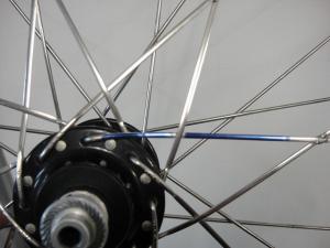
↑The spokes colored blue in this image are 8-cross inpokes,
and they're nearly perpendicular to the radial line.
Close to the tangent to the circle (hub flange). Tangential lacing's "tangent" means
tangent line, so this is literally tangent lacing.
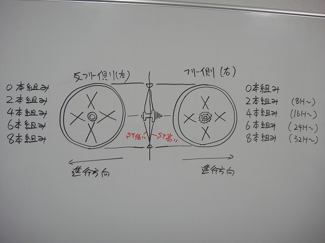
When doing 0 through 8-cross, here's what hub hole counts make each possible.
I'll use y≦4/x. Really handy, this.

When viewing a wheel from front-to-back, I usually draw it from straight behind,
but this time let's say I'm viewing from straight above.
The eyes that look sharp... well, yes.
But that's not related to Sharp the company.
If Sharp ever designed a bicycle wheel, they'd definitely
add a Plasmacluster to it.
If a wheel with a Plasmacluster-generating hub rides along
and we blow a cough bug from the front,
thanks to the negative ion effect,
it becomes a beautiful cough bug.
Never mind the cough bug (why did I even write that?),
let me look at a wheel without a tire from above.
Let's say the valve hole is straight up.
Let me take this wheel and slice it open with the magic knife from the Inpoke Part 1 entry
(→here).
I'll slice carefully to avoid the rim holes,
and cut the hub straight in half.
The sprocket side makes it clear which direction is forward.
Both sides being radial lacing is just for visibility, so let's ignore that.
This time I'm not flattening it, just opening it.
It's like a clam opened to its maximum.
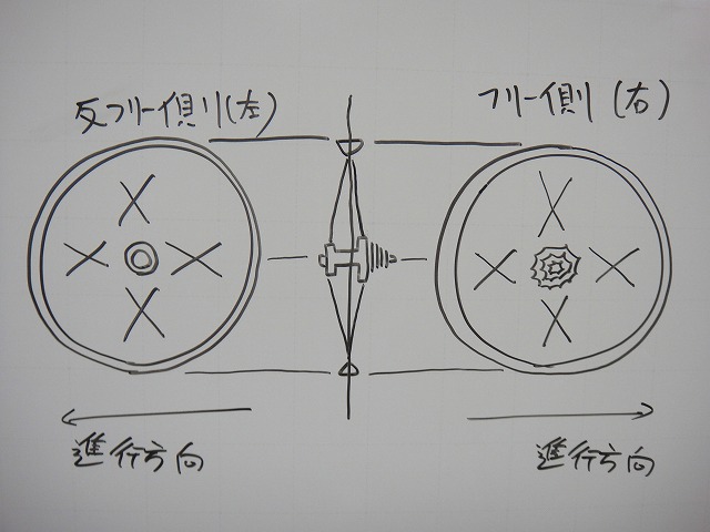
Looking at this from the brake-zone side rather than the rim's cut face
gives you the diagram above.
Last time I mentioned that since rear wheels have dish,
the freewheel side has higher spoke tension.
In the diagram above, both sides are tangential lacing.
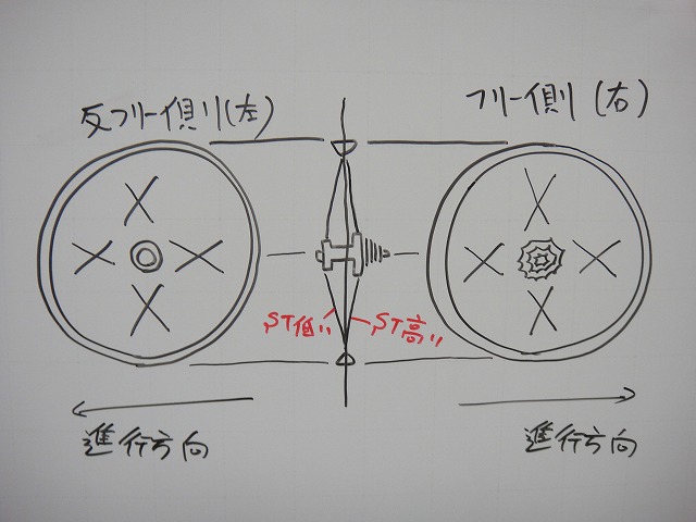
↑If the non-freewheel side is radial laced, it looks like this.
"Both front and rear wheels all radial laced would be maximum advantage in aerodynamics and weight,
but the freewheel side gets intense torsion so let's keep that as tough
tangential lacing to resist twist." That's the thinking.
Many wheel manufacturers do this, but
Easton is the most representative. There are plenty of others.
As I mentioned earlier, radial lacing lowers spoke tension.
Since the non-freewheel side already has lower spoke tension,
lowering it further with radial lacing makes the tension differential even worse.
This is the worst way to lace a wheel from a wheel balance perspective.

My mysterious cosmic carbon wheel has radial lacing on the non-freewheel side, but
that's because of the spoke holes in the rim—
I had no choice but to lace it that way.
When you feel the non-freewheel spokes, they're quite loose.
However, with radial lacing, there's no spoke-to-spoke contact, so
you don't get that creaking noise from contact,
and the weakness on the left doesn't get noticed.
Radial lacing it with inpokes is a subtle act of rebellion.
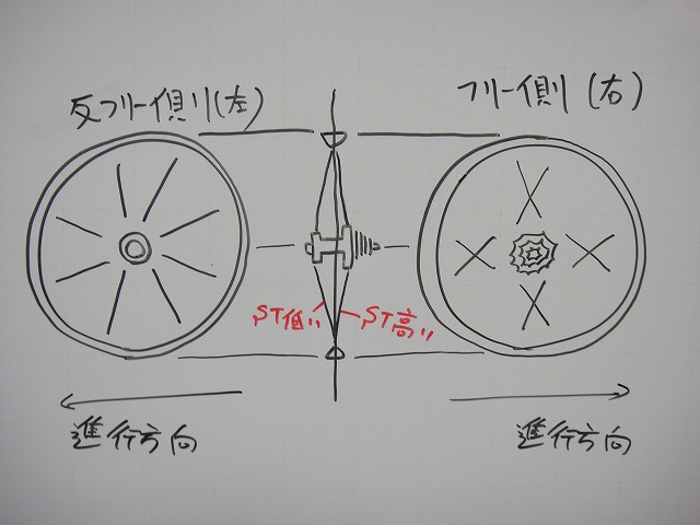
↑What if we try freewheel side radial, non-freewheel side tangential instead?
That would lower the freewheel side tension, making the left-right
balance relatively closer. This is actually the best lacing from a wheel balance perspective. But

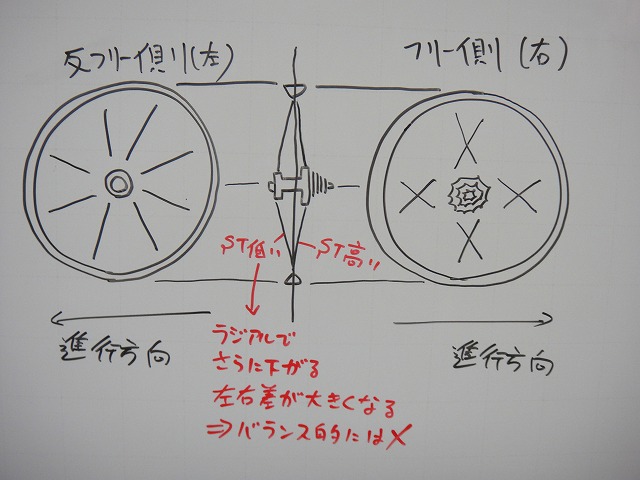
Radial lacing is
↑weak to this kind of torsion.
The torsion on the front wheel is only from rim braking,
so it's not a big issue, but on the rear freewheel side, the pedaling-driven
freewheel body twist is extreme, so problems arise.
I've actually tried freewheel-side radial on a hand-built wheel.
This is inpoke radial, and there's a reason for that.
With outpoke radial, it's hard to secure lateral stiffness.
The lateral stiffness calculation is based on where the spoke leaves the hub flange,
and with outpokes that's extremely narrow.
Plus, radial lacing lowering spoke tension means it also resists
the freewheel's intense torsion less well.
In hand-built wheel construction, this outpoke radial
is actually the worst lacing for spoke neck breakage risk.
On the other hand, inpoke radial lacing means
the spokes aren't woven, so lateral spoke spread increases,
which causes the derailleur cage to contact spokes when in low gear—
a problem that easily occurs.
There are workarounds, but even with them, climbing out of the saddle or
hard pedaling on flats can cause contact, so this lacing should be avoided.
2-cross is woven, so
2-cross inpoke → risk of derailleur contact
2-cross outpoke → low lateral stiffness
Neither is recommended.
But freewheel-side radial has major benefits for correcting spoke tension differential. What can we do...
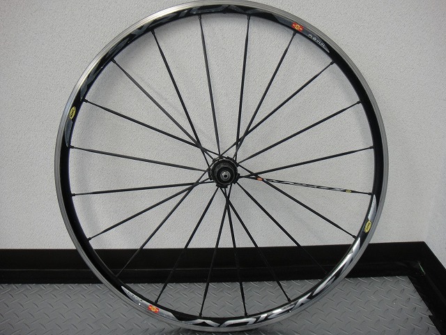
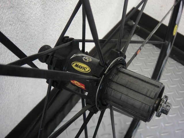
↑"What if we custom-designed the hub and spokes with large-diameter aluminum spokes?"
That incredibly smart wheel is "Kyserium." Kyserium coming in!
Looking at the freewheel body structure, the spokes don't seem to deform from freewheel torsion,
and the aluminum spokes look robust as can be.
For Mavic to think this up in 1999 shows how ahead they were.
This is speculation on my part, but I think Kyserium's starting point was
not "let's make a wheel with aluminum spokes"
but rather "let's make a freewheel-side radial wheel."
The pursuit of structure that could withstand freewheel torsion undaunted
is what led to adopting aluminum spokes, I believe.
~Tangent~
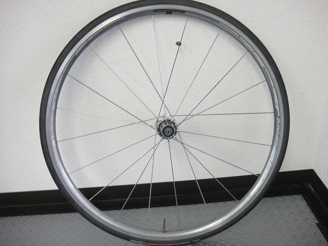
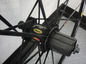
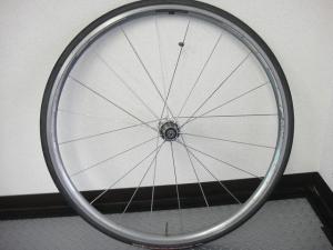
↑This is a 7800-series Dura-Ace pre-built wheel.
Freewheel-side radial. In current models, Zipp wheels and
Mavic's Kyserium Elite have steel spokes with radial lacing, and
with straight spokes' high-tension capability and smart hub design,
they manage steel spokes in freewheel-radial without issues.
This wheel similarly has steel spokes with freewheel-radial.

People often complain that Dura-Ace wheels from this era are "hard to adjust,"
but that has nothing to do with whether the wheel rides well or not, so it doesn't matter.
It's my job to fix them anyway.
The hub internals are a straight copy of Campagnolo's
and the lacing is a straight copy of Kyserium's, but in terms of how thoroughly the wheel logic is thought through,
I think this is Shimano's greatest rear wheel ever made.
After this, they start thinking for themselves, which actually produces mediocre wheels.
They've pushed the left flange position way out. Clever!
WH-9000 calls itself wide-flange, but the width is about the same as this.
They call it extra-wide-flange, but
even back in the WH-7800 era it was basically extra-wide-flange.
And then they trash-talk their own previous product (WH-7900) from yesterday. That's bold.
~End tangent~
Thanks to T-san for helping photograph these wheels.
That wheel's a masterpiece, so don't you dare sell it.
Freewheel-side radial is only possible with pre-built wheels!
(You can only read this manga in Jump!)
So I want to think about
Related Products on Amazon
* Amazon affiliate links — prices may vary
Original Japanese post: のむラボ日記 #76